Lighting device and method

A lighting device and confocal technology, applied in the field of biomedical microscopic imaging, can solve the problems of high requirements for fluorescence anti-fade, lower image signal-to-noise ratio, and increase the difficulty of scientific research experiments, etc., to achieve the effect of improving axial resolution

Inactive Publication Date: 2015-12-30
谢赟燕
View PDF7 Cites 8 Cited by
  • Summary
  • Abstract
  • Description
  • Claims
  • Application Information

AI Technical Summary

Problems solved by technology

This shows that using conventional illumination methods, the illumination of the sample 17 located on the non-focal plane of the microscope objective lens 9 cannot be avoided, and the signal of the sample 17 located on the non-focal plane of the microscope objective lens is relative to the signal of the sample 10 located on the focal plane of the microscope objective lens. It is the image noise of the confocal imaging system, which reduces the signal-to-noise ratio of the image and reduces the axial resolution of the confocal imaging system
[0004] In addition, the confocal microscopy imaging system using a traditional collimated light sour

Method used


Image

  • Lighting device and method
  • Lighting device and method
  • Lighting device and method

Examples


Embodiment 1

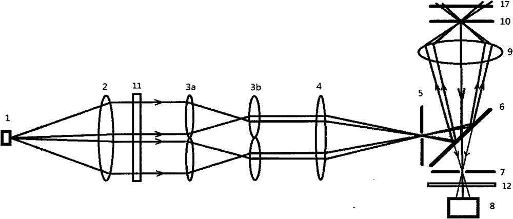
[0029] figure 1 It is a schematic diagram of the first illumination device related to the present invention used in confocal imaging system fluorescence imaging: the light emitted by the light source 1 is collimated into a parallel beam through the collimating mirror 2; the parallel beam passes through the excitation filter 11 Filter to obtain parallel excitation light of a specific wavelength band; the parallel excitation light is converged into an annular aperture by the first annular lens 3a, and then the annular aperture is collimated into an annular parallel excitation light by the second annular lens 3b, the second The two annular lenses 3b are annular convex lenses; the annular parallel excitation light is converged by the converging lens 4 through the illumination pinhole 5 of the confocal imaging system, reflected by the dichroic beam splitter 6 and passed through the microscope objective lens 9. Excite the sample 10 located at the focal plane of the microscope objec...

Embodiment 2

[0031] image 3 It is a schematic diagram of the second illuminating device related to the present invention used in confocal imaging system fluorescence imaging, and the difference from Embodiment 1 is as follows: the second annular lens 3b is an annular concave lens; excitation filter 11, emission filter 12 and the sample 17 located on the non-focal plane of the microscope objective lens are not shown.

Embodiment 3

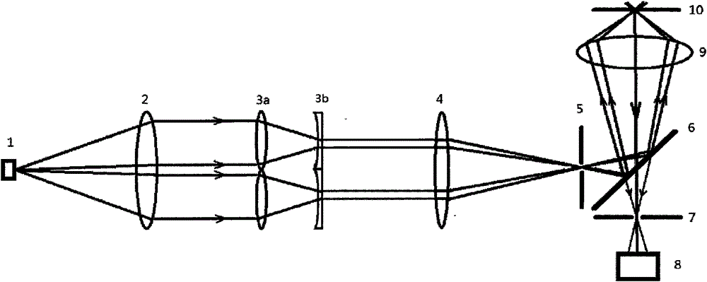
[0033] Figure 4 It is a schematic diagram of the third illumination device related to the present invention used in confocal imaging system fluorescence imaging, and the difference from Embodiment 1 is as follows: replace the first annular lens 3a and the second annular lens 3b with an annular diaphragm 13 Although the annular lens group reduces the utilization efficiency of the light source, it reduces the manufacturing difficulty and cost; the excitation filter 11, the emission filter 12 and the sample 17 located on the non-focal plane of the microscope objective lens are not shown.


PUM


Abstract

The present invention relates to a lighting device and a method, particularly relating to a lighting device for improving axial resolution of a confocal microscope imaging system. The lighting device mainly comprises a collimating lens, an annular lens with a long focal length, an annular lens with a short focal length, and a converging lens whose one focal point is in a confocal imaging system lighting needle hole, wherein the focal points of the two annular lenses coincide. According to the device, the lighting light from the light source is shaped into annular parallel beams, after convergence, the beams illuminate a sample through the lighting needle hole of the confocal imaging system and an object lens. Compared with a traditional lighting mode, according to the device, the axial illumination to an object lens non-focal plane sample is reduced, the reflection light or emitted fluorescence from the non-focal plane sample collected by the confocal imaging system is reduced, and thus the noise of an image is reduced and the signal to noise ratio of the image is raised. Thus, the axial resolution of the confocal microscope imaging system can be raised by the lighting device.

Description

technical field [0001] The invention relates to an illuminating device and method, in particular to an illuminating device for improving the axial resolution of a confocal microscopic imaging system. The invention is mainly used in the field of biomedical microscopic imaging, and can also be used in material research and integrated circuit chip detection imaging. Background technique [0002] With the deepening of cell biology research, the application of fluorescence microscopy imaging is becoming more and more common, and confocal microscopy imaging has received more and more attention. The current confocal imaging system uses a traditional, uniform light source. The illumination light passes through the pinhole through the lens, and then illuminates the sample through the objective lens of the microscope. Finally, the detector collects the sample reflected or emitted by the objective lens and the pinhole. optical signal to obtain confocal images with a certain axial reso...

Claims


Application Information

Patent Timeline
IPC IPC(8): G02B21/08G01N21/01G01N21/64
Inventor 谢赟燕
Owner 谢赟燕
Why Eureka
Try Eureka