Light source system and projection equipment
A light source system and light source technology, applied in the field of optics, can solve the problems of low utilization efficiency of red light and achieve the effect of avoiding light loss and improving light utilization
- Summary
- Abstract
- Description
- Claims
- Application Information
AI Technical Summary
Problems solved by technology
Method used
Image
Examples
Embodiment 1
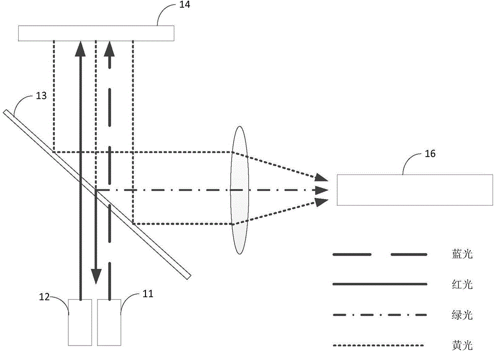
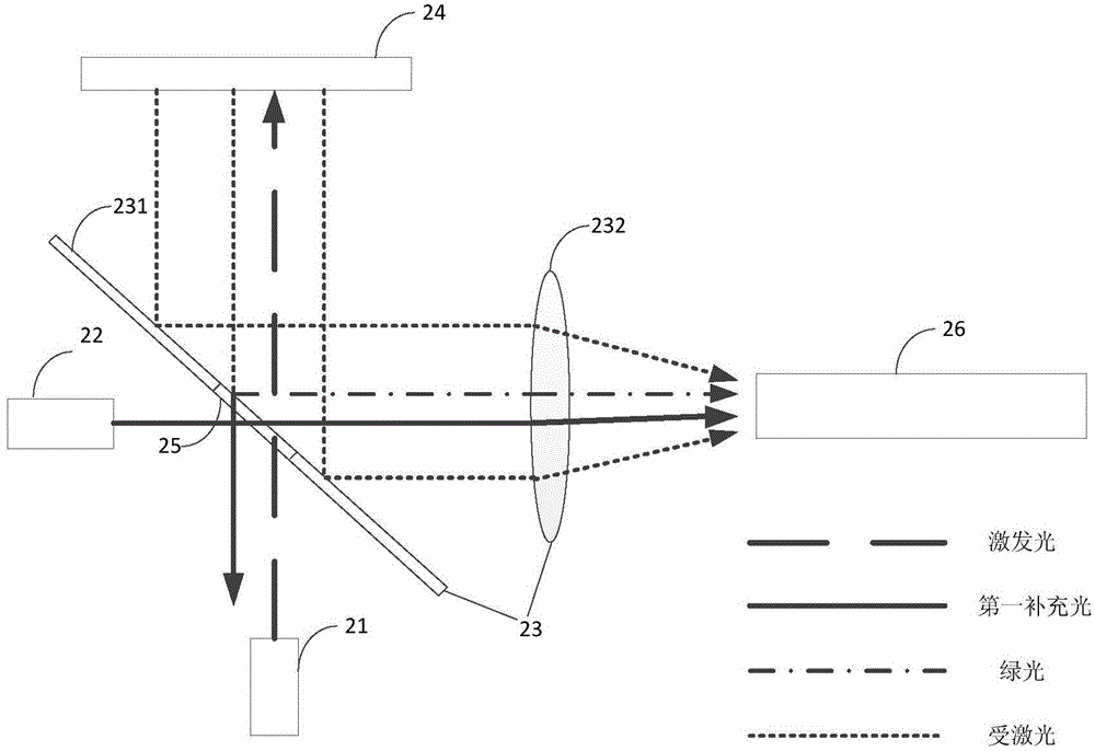
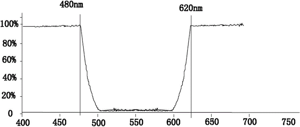
[0046] This embodiment provides a light source system, such as figure 2 As shown, the light source system includes two light sources, respectively an excitation light source 21 and a first supplementary light source 22 , and also includes a first light guiding component 23 , a wavelength converting device 24 , a second light guiding component 25 and a light homogenizing device 26 . In this embodiment, the first light guiding component 23 and the second light guiding component 25 realize light splitting and combination by using wavelengths. The first light guiding component 23 includes a filter 231 having a central film and edge films, and the second light guiding component 25 is the central film of the filter 231 . in:
[0047] The excitation light source 21 emits excitation light. The excitation light source 21 is a semiconductor diode or a semiconductor diode array. The semiconductor diode may be a laser diode (LD) or a light emitting diode (LED). The excitation light i...
Embodiment 2
[0066] This embodiment provides another light source system, please refer to Figure 4 , the light source system and figure 2 The difference of the light source system shown is that the second light guiding member 25 realizes light splitting and combining by means of etendue. Specifically, it is replaced by a reflective sheet 431 with a through hole figure 2 A filter 231 with a central diaphragm and edge diaphragms. In this embodiment, the first light guiding component 43 includes a reflective sheet 431 having a through hole, and the second light guiding component 25 is the through hole on the reflective sheet 431 .
[0067] Wherein the size of the through hole is smaller than the size of the reflection sheet 431 . The size of the through hole can be determined according to one or more combinations of the light loss when the first supplementary light passes through the through hole, the light loss when the excitation light passes through the through hole, and the light lo...
Embodiment 3
[0070] This embodiment provides another light source system, such as Figure 5 As shown, the light source system and figure 2 The difference of the light source system shown is that the second light guiding component realizes light splitting and combining by using polarization state. Specifically: the optical filter 531 in the light source system includes a polarizer and an edge film, wherein the edge film is the same as the edge film in Embodiment 1, and the difference is that figure 2 The central diaphragm of the middle optical filter 231 is replaced by a polarizer.
[0071] In this embodiment, the first light guiding component 53 is a filter 531 having a polarizer and an edge film, and the second light guiding component 25 is a polarizing plate in the filter 531 . The polarizer reflects light having a first polarization state and transmits light having a second polarization state. Wherein the first polarization state is the P state and the second polarization state is ...
PUM
 Abstract
Description
Claims
Application Information
 - R&D
- Intellectual Property
- Life Sciences
- Materials
- Tech Scout
- Unparalleled Data Quality
- Higher Quality Content
- 60% Fewer Hallucinations
Browse by: Latest US Patents, China's latest patents, Technical Efficacy Thesaurus, Application Domain, Technology Topic, Popular Technical Reports.
© 2025 PatSnap. All rights reserved.Legal|Privacy policy|Modern Slavery Act Transparency Statement|Sitemap|About US| Contact US: help@patsnap.com


