
Micro-step drive control method of permanent magnet synchronous motor

A permanent magnet synchronous motor, micro-step technology, applied in motor generator control, electronic commutation motor control, control system and other directions, can solve problems such as control instability

Inactive Publication Date: 2015-12-30
BEIJING INST OF CONTROL ENG
View PDF4 Cites 5 Cited by
  • Summary
  • Abstract
  • Description
  • Claims
  • Application Information

AI Technical Summary

Problems solved by technology

[0006] The technical problem solved by the present invention is: to overcome the deficiencies of the prior art, and to solve the problem that the existing solar panel drive mechanism adopts the direct drive closed-loop control scheme of the permanent magnet synchronous motor, in the face of large load inertia, weak damping, large flexibility, etc. In the case of unstable control, a micro-step drive control method for permanent magnet synchronous motors is proposed, which has good positioning performance for large inertia loads, and has strong robustness, high reliability, and good control effects

Method used


Image

  • Micro-step drive control method of permanent magnet synchronous motor
  • Micro-step drive control method of permanent magnet synchronous motor
  • Micro-step drive control method of permanent magnet synchronous motor

Examples


Embodiment Construction

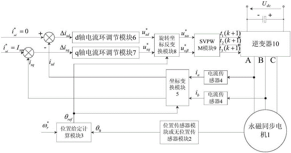
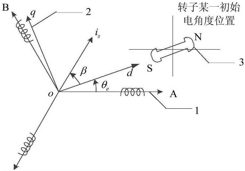
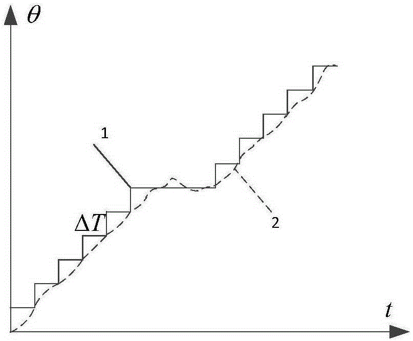
[0036] A permanent magnet synchronous motor micro-step drive control method, based on the permanent magnet synchronous motor field-oriented vector control, the goal is to control the permanent magnet synchronous motor rotor to rotate at a constant speed with the given position of the stator current vector. The realization principle is based on The principle of permanent magnet synchronous motor rotor field orientation, when a current vector is given at a fixed position, the positive direction of the permanent magnet of the permanent magnet synchronous motor rotor (direction of the N pole) is fixed at the given position.

[0037] The method of the present invention adopts the following technical solutions: figure 1 The control system required for a micro-step drive control method of a permanent magnet synchronous motor according to the present invention includes a permanent magnet synchronous motor 1, a position sensor or a position sensorless rotor position detection module 2, a p...


PUM


Abstract

The invention provides a micro-step drive control method of a permanent magnet synchronous motor. The method comprises the steps that a current position of a permanent magnet synchronous motor rotor is detected through a position sensor, and the position of the rotor at the next moment is obtained through calculation; a current value of a permanent magnet synchronous motor stator is detected, and a stator three-phase current of the permanent magnet synchronous motor and a current component under a two-phase static coordinate system are obtained; a current component under a synchronous rotating coordinate system is obtained according to the position of the permanent magnet synchronous motor at the next moment and the current component under the two-phase static coordinate system; a current difference value is obtained finally, a reference voltage, an SVPWM reference input voltage and the three-phase PWM duty ratio under the synchronous rotating coordinate system are generated, a drive voltage of a next cycle is obtained, and drive is completed. By means of the micro-step drive control method of the permanent magnet synchronous motor, the defect that for an existing closed-loop control scheme, when the situations that load inertia is large, control is not stable is overcome, good positioning performance for a large inertial load is achieved, the robustness is strong, the reliability is high, and the control effect is good.

Description

Technical field [0001] The invention relates to a micro-step drive control method of a permanent magnet synchronous motor, in particular to a control method in which a solar sailboard driving device adopts a permanent magnet synchronous motor to drive the micro-step drive. Background technique [0002] In order to meet the energy requirements of spacecraft working in orbit, most spacecraft use windsurfing solar arrays. In order to maximize the utilization of solar cells, solar windsurfing drive devices are usually used to drive the solar windsurfing boards to achieve orientation towards the sun. . The solar panel drive device uses a permanent magnet synchronous motor to directly drive a closed-loop control scheme. There is no deceleration device between the drive mechanism and the flexible load. Any characteristics and disturbances of the load will be transmitted to the output shaft of the drive motor without reservation. Under normal circumstances, the inertia of the solar sail...

Claims


Application Information

Patent Timeline
IPC IPC(8): H02P21/00
Inventor 郭超勇陆栋宁张猛程俊波王友平梁骄雁于国庆
Owner BEIJING INST OF CONTROL ENG
Learn More