
Pseudo-thermal light source based on array light beam

A technology of pseudothermal light source and array beam, which is applied in optics, optical components, nonlinear optics, etc., can solve the problems of low intensity fluctuation rate and low output power, and achieve the effect of improving brightness and good repeatability

Active Publication Date: 2016-01-06
XIDIAN UNIV
View PDF9 Cites 6 Cited by
  • Summary
  • Abstract
  • Description
  • Claims
  • Application Information

AI Technical Summary

Problems solved by technology

[0007] The purpose of the present invention is to provide a high-brightness, fast time-varying pseudothermal light source, which can solve the problems of low output power and low intensity fluctuation rate of existing pseudothermal light sources

Method used


Image

  • Pseudo-thermal light source based on array light beam
  • Pseudo-thermal light source based on array light beam
  • Pseudo-thermal light source based on array light beam

Examples


Embodiment Construction

[0025] The present invention will be described in detail below in conjunction with the accompanying drawings. When describing the embodiments of the present invention in detail, for the convenience of explanation, the accompanying drawings showing the structure of the device will not be partially enlarged according to the general scale, and the schematic diagram is only an example, and it should not be limited here. The protection scope of the present invention. It should be noted that all the drawings are in very simplified form and use imprecise scales, which are only used to facilitate and clearly assist the purpose of illustrating the embodiments of the present invention.

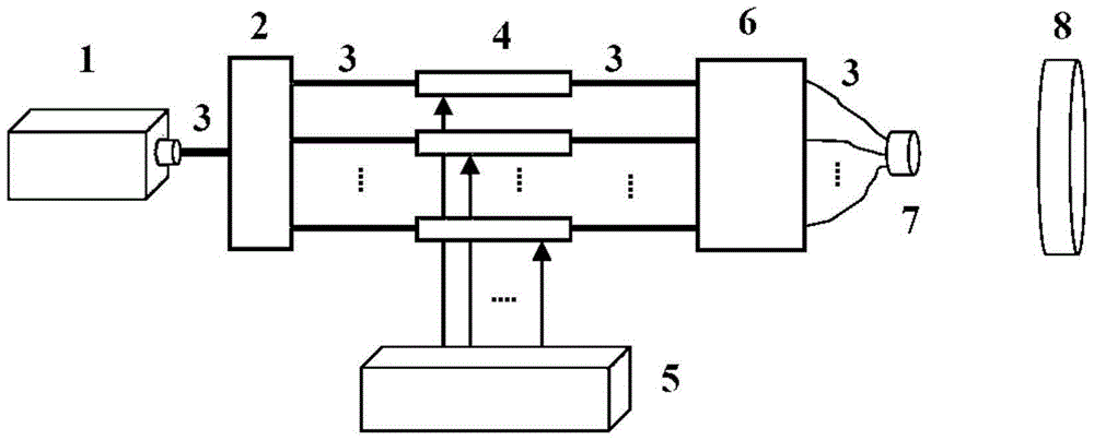
[0026] Such as figure 1 As shown, the pseudothermal light source of the present invention includes a pulsed laser 1, a fiber coupler 2, an electro-optical phase modulator 4, a radio frequency drive power supply 5, an optical fiber amplifier 6, an array of fiber bundles 7 and a beam expander collimator 8...


PUM

PropertyMeasurementUnit
Diameteraaaaaaaaaa

Abstract

The invention discloses a pseudo-thermal light source based on an array light beam. The pseudo-thermal light source comprises a pulse laser, a fiber coupler, an electro-optic phase modulator, a radio frequency driving power supply, a fiber amplifier, a fiber bundle array and a beam expansion collimator, wherein the pulse laser, the fiber coupler, the electro-optic phase modulator, the fiber amplifier and the fiber bundle array are successively connected through single-mode fibers, and the electro-optic phase modulator is driven by the radio frequency driving power supply; and laser emitted by the pulse laser, after being divided into multiple beams of coherent light by the fiber coupler, is transmitted to the electro-optic phase modulator for random phase modulation, then is transmitted to the fiber amplifier for power amplification, and then is output through the fiber bundle array and the beam expansion collimator. The pseudo-thermal light source provided by the invention can solve the problems of low output power and low intensity fluctuation rate existing in a conventional pseudo-thermal light source and realizes the effects of high brightness and rapid time-variation.

Description

technical field [0001] The invention relates to a thermal light field and an optical system, in particular to a device for generating a pseudothermal light source. Background technique [0002] Due to the characteristics of light intensity correlation and good atmospheric transmission characteristics, artificially regulated pseudothermal light has a wide range of applications in the fields of optical correlation imaging, laser target detection and wireless optical communication. In the visible and near-infrared bands, the existing pseudothermal light mainly has two types of generation methods based on rotating frosted glass and liquid crystal light valve. The earliest pseudothermal light was designed and invented by Martienssen and Spiller in 1964. It was produced by continuous laser light through rotating ground glass. The disadvantage is that it does not meet the cross-spectrum pure condition of thermal light. [0003] To solve this problem, the Chinese invention patent w...

Claims


Application Information

Patent Timeline
IPC IPC(8): G02B27/10G02F1/035
CPCG02B27/1006G02F1/035
Inventor 刘春波韩香娥卢芳
Owner XIDIAN UNIV
Features
  • Generate Ideas
  • Intellectual Property
  • Life Sciences
  • Materials
  • Tech Scout
  • Unparalleled Data Quality
  • Higher Quality Content
  • 60% Fewer Hallucinations
Learn More