Solar module and preparation method thereof
A technology of solar cells and solar cells, which is applied in the field of solar cells and can solve problems such as easy leakage
- Summary
- Abstract
- Description
- Claims
- Application Information
AI Technical Summary
Problems solved by technology
Method used
Image

Examples
preparation example Construction
[0045] The preparation method of the solar cell module of one embodiment, such as image 3 shown, including the following steps:
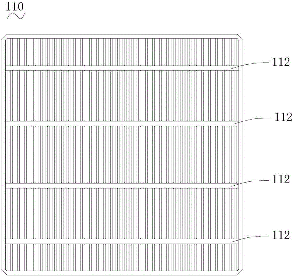
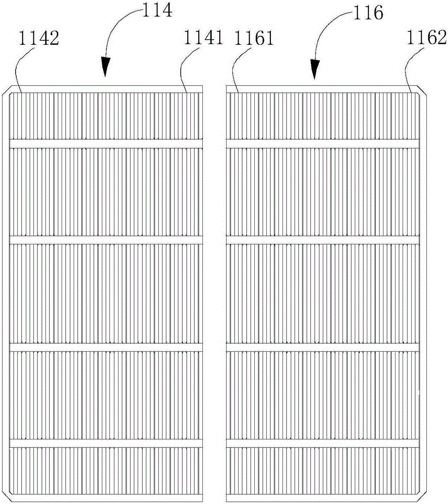
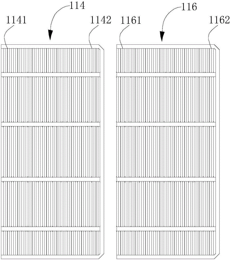
[0046] S10 , providing a battery cutting sheet, which is formed by cutting the solar battery sheet along an extending direction perpendicular to the busbar, and has a cut end and an uncut end disposed opposite to each other.
[0047] In a preferred embodiment, the cell cutting sheet is formed by cutting the solar cell sheet along its back side. Lasers can be used to cut solar cells. Since laser cutting has an oxidation effect at the same time, the insulation effect is enhanced and the risk of leakage can be reduced.
[0048] S20. Connect the battery cut sheets in two adjacent steps S10 in series with a connector, so that one end of the connector is connected to the front electrode of the battery cut sheet at the uncut end, and the other end passes through the uncut end of the battery cut sheet to be adjacent to it The gaps between the cutting end...
Embodiment 1
[0055] The solar cell assembly of this embodiment includes five series-connected battery groups, each battery group includes two parallel-connected cell strings, and each cell string includes twelve series-connected cut-off cells. Each cell cut sheet is formed by cutting the solar cell sheet in half along its back side with a laser.
[0056] The circuit diagram of the solar cell assembly of the present embodiment is as follows Figure 4 shown. In addition, due to the hot spot characteristics of solar cells, under certain conditions, a shaded solar cell in a series branch will be used as a load to consume energy generated by other illuminated solar cells. The shaded solar cell assembly will generate heat at this time, which will affect the efficiency of a string of solar cell sheets, resulting in lower efficiency of the entire solar cell assembly. Therefore, in this embodiment, one diode 120 is connected in parallel to each battery group, and five diodes 120 are connected in ...
Embodiment 2
[0058] The difference between this embodiment and Embodiment 1 is that the solar cell assembly of this embodiment includes six battery packs connected in series, and each battery pack includes two strings of battery slices connected in parallel, and each string of battery slices Consists of ten battery cut sheets connected in series with each other.
[0059] In addition, refer to Figure 5 , in this embodiment, a diode 220 is connected in parallel for every two battery packs. In this way, the diodes 220 are connected in parallel to the four battery strings in every two battery groups, and three diodes 220 are connected in parallel in the whole solar cell module.
PUM
 Abstract
Description
Claims
Application Information
 - R&D
- Intellectual Property
- Life Sciences
- Materials
- Tech Scout
- Unparalleled Data Quality
- Higher Quality Content
- 60% Fewer Hallucinations
Browse by: Latest US Patents, China's latest patents, Technical Efficacy Thesaurus, Application Domain, Technology Topic, Popular Technical Reports.
© 2025 PatSnap. All rights reserved.Legal|Privacy policy|Modern Slavery Act Transparency Statement|Sitemap|About US| Contact US: help@patsnap.com