A detachable plate type indirect heating coal pyrolysis device

A coal pyrolysis and indirect technology, applied in the field of coal quality improvement, can solve the problems of not obvious improvement of heat transfer efficiency, affecting product quality, affecting heat exchange efficiency, etc., to ensure high efficiency and sustainability, and to facilitate cleaning and replacement , Increase the effect of heat exchange efficiency

Active Publication Date: 2019-10-22
CHANGZHENG ENG
View PDF10 Cites 8 Cited by
  • Summary
  • Abstract
  • Description
  • Claims
  • Application Information

AI Technical Summary

Problems solved by technology

[0006] In the existing technology, the indirect coal pyrolysis heat exchange system usually adopts a tube-and-tube heat exchange structure. Due to a large number of welded connections, the heat exchange structure is not easy to disassemble, the tubes are easy to block, the maintenance period is short, and the maintenance cost is high.
[0007] The publication number is CN102911677A, which discloses a heat-carrying gas pyrolysis device for coal. The device uses heat-carrying gas to indirectly heat coal through metal heat transfer tubes for pyrolysis. The disadvantages are: (1) inside the heat transfer tube The baffle only increases the turbulent flow of the heat-carrying gas, but the gas-solid heat transfer coefficient is determined by the heat transfer of the solid-phase medium outside the tube. The heat absorption efficiency of the coal side is not improved, and the heat transfer efficiency of the whole system is not significantly improved; (2) The composition of the heat-carrying gas heat transfer system is complicated, and there are too many solder joints, which cause great hidden dangers to the operation safety; (3) It is difficult for the coal to enter the retort chamber from the coal charging hole, and the uneven distribution in the room affects the heat transfer efficiency; (4) The device is only suitable for normal-pressure pyrolysis, and high-temperature semi-coke co-production of natural gas and syngas needs to be boosted, which affects the economics of the entire process device
The disadvantages of this pyrolysis furnace are: (1) there is a certain requirement for the purity of the gas heat carrier in the tube, otherwise the pores on the gas distributor are easy to block; (2) the high-temperature gas directly contacts with the coal and is discharged together with the pyrolysis gas. Increase the amount of downstream gas purification, increase the energy consumption and difficulty of dust removal, and affect product quality; (3) There may be no coal powder under the conical surface of the distributor, there is a heat exchange dead zone, and the pyrolysis pressure drop may be very large high

Method used


Image

  • A detachable plate type indirect heating coal pyrolysis device
  • A detachable plate type indirect heating coal pyrolysis device
  • A detachable plate type indirect heating coal pyrolysis device

Examples


Embodiment 1

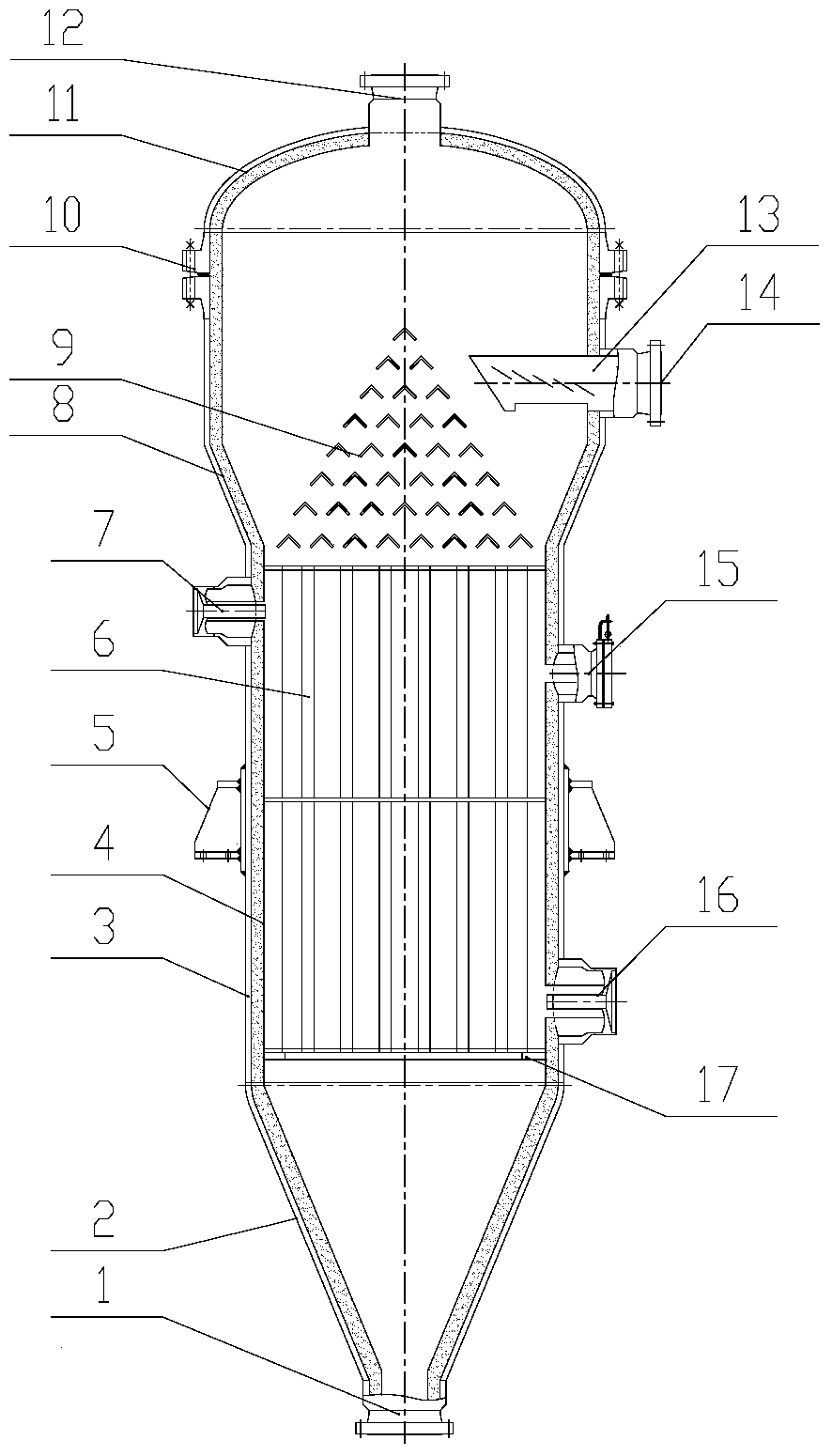
[0039] Please refer to figure 1 , figure 1 It is a structural schematic diagram of the coal pyrolysis device of the present invention.

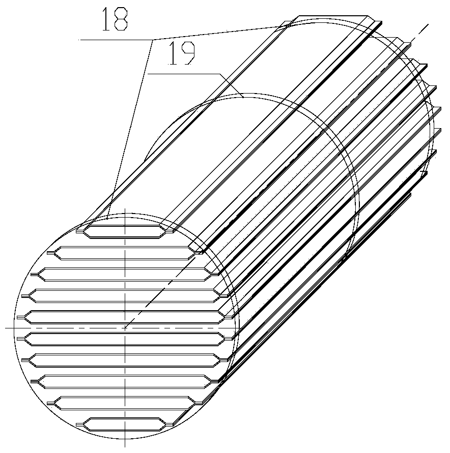
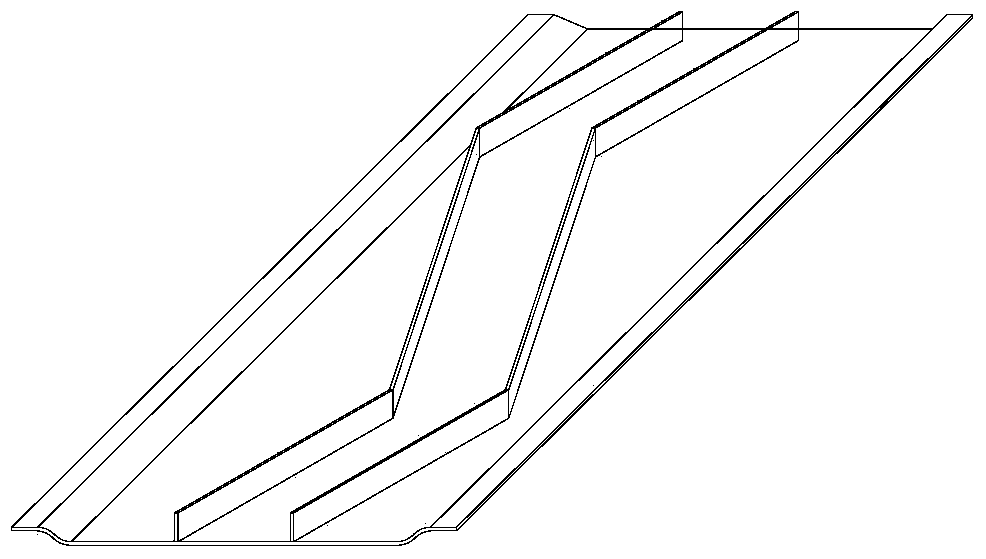
[0040] The present invention provides a detachable plate-type indirect heating coal pyrolysis device, which includes a shell, a coal distributor 9 and a detachable modular heat exchange system.

[0041] The shell is composed of a lower head 2 , a lower cylinder 3 , an upper cylinder 8 and an upper head 11 . Among them, the lower head 2 is funnel-shaped, and the lower cylinder 3 is a cylinder. The lower head 2 and the lower cylinder 3 are welded into one body according to the requirements of the pressure vessel. The material port 1, the lower part of the lower cylinder body 3 is provided with a high-temperature gas inlet 16, and the upper part is provided with a high-temperature gas outlet 7 and a manhole 15. The upper cylinder 8 has an enlarged section, the diameter of which is larger than that of the lower cylinder 3, and the upper head 1...

Embodiment 2

[0047] The preferred embodiment of the present invention is the cogeneration process of lignite pyrolysis gasification, mainly using the synthetic gas produced by dry coal gasification as the heat source of lignite pyrolysis, and the high temperature and high pressure semi-coke produced by lignite pyrolysis is directly fed into the gas Furnace as raw material for gasification. After drying, the lignite pulverized coal enters the pyrolysis device of the present invention from the coal feed port 12 on the top of the equipment after being lifted to about 4.5MPa, and enters into the plate tubes arranged in parallel through the coal distributor 9, and the pulverized coal moves downward at a certain speed . Synthesis gas at 4.5MPa and about 800°C produced by the dry coal pulverized gasifier enters the flow channel between the plates and tubes from the high-temperature gas inlet 16 of the lower cylinder 3, and indirectly heats the lignite on the other side of the plate to about 550°C...


PUM


Abstract

The invention relates to a coal pyrolysis device, belongs to the technical field of coal quality improvement, and relates to a detachable plate type indirect heating coal pyrolysis device which comprises a casing. The top of the casing is provided with a coal feeding port and a pyrolytic gas outlet. The bottom of the casing is provided with a semi-coke discharging port. A detachable modularized heat exchange system is arranged below the coal feeding port in the casing and comprises one or more heat exchange modules in series connection in sequence. Each heat exchange module comprises a plate bundle, a tube plate and a supporting plate, at least one supporting plate is axially arranged on the circumference of the plate bundle, and the two ends of the plate bundle are fixed to the tube plate. The plate bundle is connected with the tube plate through a high temperature resistant expanding material. Along with the changes of environment temperature, the plate bundle and the tube plate are fastened or separated, and the heat exchange modules and the whole heat exchange system are detachably replaceable. Coal and high temperature gas undergo indirect type heat exchange in reverse flows on the two sides of a plate slice to achieve coal pyrolysis, so that high-quality pyrolysis gas is obtained, and energy consumption of a purification system is reduced.

Description

technical field [0001] The invention relates to a coal pyrolysis device, which belongs to the technical field of coal quality improvement, in particular to a detachable plate type indirect heating coal pyrolysis device. Background technique [0002] my country is a big coal producing country in the world, and it is also a big coal consuming country. In 2010, my country's proven reserves of coal resources accounted for 93.3% of my country's fossil energy. China's energy reserves, production and consumption structure determine that coal will remain my country's main energy source for a period of time to come. [0003] At present, my country's coal industry has problems such as serious environmental pollution, low coal utilization rate, and unreasonable energy utilization. With the development and progress of coal resource utilization technology, coal quality-based utilization technology has become more and more the direction of technology development and the hot spot of coal ...

Claims


Application Information

Patent Timeline
Patent Type & Authority Patents(China)
IPC IPC(8): C10B53/04C10B47/02
Inventor 甘晓雁刘春雷马超林东杰
Owner CHANGZHENG ENG
Why Eureka
Try Eureka