Aerodynamic brake of high-speed train

A technology for aerodynamic braking and high-speed trains, applied in the direction of pneumatic brakes, hydrodynamic brakes, hydrostatic brakes, etc., can solve the problems of traction power consumption, increased impact vibration, radial cracks on the friction surface of brake discs, etc. Achieve the effects of shortening the time required for braking, reducing the probability of accidents, and making small changes to the car body structure

Active Publication Date: 2016-01-20
上海洲跃生物科技有限公司
View PDF5 Cites 6 Cited by
  • Summary
  • Abstract
  • Description
  • Claims
  • Application Information

AI Technical Summary

Problems solved by technology

However, with the increase of train speed and kinetic energy, the heat energy generated during braking also increases greatly in the disc brake mode. The huge brake heat load makes the brake disc prone to thermal fatigue damage, which is mainly manifested in the alternating temperature Mechanical damage, tissue degeneration and oxidative corrosion under the simultaneous action of alternating thermal stress will produce radial cracks on the friction surface of the brake disc in severe cases, which will easily lead to brittle fracture of the brake disc and affect driving safety. Problems such as high-temperature creep, high-temperature oxidation, and frictional heat on the surface cause material softening. In addition, the brake disc increases the unsprung weight and the impact vibration caused by it; traction power is also consumed during operation, and the higher the speed, the higher the power. The greater the loss
[0011] Although dynamic braking has high efficiency and is widely used in conventional braking, due to the complex design of the braking device, high installation accuracy, and many pipelines, in unexpected cases, electrical failures may occur on the train and cause power loss. Braking can only be used as an alternative means and not as the ultimate means of braking
[0012] It can be seen from Table 2 that the current braking methods generally have the problem of excessively long braking distances. In terms of comfort, it has become increasingly difficult to meet the operating requirements of high-speed trains with speeds above 300km / h

Method used


Image

  • Aerodynamic brake of high-speed train
  • Aerodynamic brake of high-speed train
  • Aerodynamic brake of high-speed train

Examples


Embodiment Construction

[0028] Describe the implementation process of the present invention in detail below in conjunction with accompanying drawing

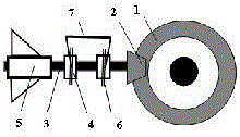
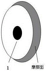
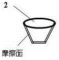
[0029] Such as Figure 1~3 As shown, the device of the present invention includes a shaft disk 1, a friction wheel 2, a rotating shaft 3, a bearing 4, an impeller 5, a fastening ring 6, a pincer rod 7 and a driving mechanism 8;

[0030] 1) Cutting the outer edge of the shaft disc 1 into a conical friction surface;

[0031] 2) Install the axle disk 1 on the axle with an interference fit;

[0032] 3) Assemble the inner rings of the two rolling bearings 4 with an interference fit at the middle position of the rotating shaft 3;

[0033] 4) Install the impeller 5 on one end of the rotating shaft 3 with an interference fit;

[0034] 5) Install the friction wheel 2 on the other end of the rotating shaft 3 with an interference fit;

[0035] 6) Hoop the fastening ring 6 on the outer ring of the bearing 4;

[0036] 7) Connect the fastening ring 6 with the c...


PUM


Abstract

The invention discloses an aerodynamic brake of a high-speed train. The aerodynamic brake comprises a shaft disk, a friction wheel, a rotary shaft, bearings, an impeller, fastening rings, a nippling lever and a driving mechanism. The shaft disk is arranged on an axle of the train. The impeller is arranged at one end of the rotary shaft, and the friction wheel is arranged at the other end of the rotary shaft. The two bearings are arranged on the middle section of the rotary shaft and hooped into the two fastening rings. During braking, the driving mechanism controls the nippling lever to put down the impeller and an assembly of the impeller from a skirt plate, the impeller and the assembly of the impeller make contact with and squeeze the conical friction surface of the shaft disk, the impeller rotates at high speed due to friction transmission to act on air, forward wind power is generated, and meanwhile violently collides with head-on air, kinetic energy of the train is consumed into the air, and therefore the braking aim is achieved; after braking is completed, the friction wheel is disengaged from the shaft disk, the nippling lever rises, and the impeller and the assembly of the impeller are lifted to the skirt plate. Braking is conducted based on the aerodynamic principle, braking force is large, time needed for braking can be remarkably shortened, maintenance is convenient, and the service life is long.

Description

technical field [0001] The invention belongs to the technical field of braking of railway vehicles, and relates to an aerodynamic braking device for high-speed trains. Background technique [0002] Reliable braking of high-speed trains is the basic requirement for driving safety. The braking methods of trains are divided into friction braking (also known as air braking) and dynamic braking according to the kinetic energy consumption mode; friction braking includes brake shoe braking (tread system) Dynamic), disc brake, magnetic track brake; dynamic brake includes resistance brake, regenerative brake, rotating eddy current brake, track eddy current brake, etc. According to the way of braking force formation, it can be divided into adhesive braking and non-adhesive braking. Among them, brake shoe braking, disc braking, resistance braking, regenerative braking, and rotating eddy current braking are viscous braking. Dynamic and orbital eddy current brakes are non-viscous brakes...

Claims


Application Information

Patent Timeline
Patent Type & Authority Applications(China)
IPC IPC(8): B61H11/06B61H11/14B61H1/00
Inventor 李春洲李珂
Owner 上海洲跃生物科技有限公司
Why Eureka
Try Eureka