Electromagnetic harmonic wave exciting device for high-speed rotating impeller

A technology of excitation device and high-speed rotation, which is used in measurement devices, vibration testing, and testing of machine/structural components. , Improve the stability and ensure the effect of firmness

Active Publication Date: 2016-01-20
XIAN THERMAL POWER RES INST CO LTD
View PDF5 Cites 7 Cited by
  • Summary
  • Abstract
  • Description
  • Claims
  • Application Information

AI Technical Summary

Problems solved by technology

[0004] With the continuous development of impeller machinery in the direction of high power and high efficiency, the requirements for impeller vibration testing technology under high-speed rotation are also increasing. Whether contact or non-contact rotating impeller vibration measurement methods are used, the rotating impeller needs to be tested. Excitation, while the traditional excitation method of injecting nitrogen gas to the rotating impeller can only provide a constant excitation force, and cannot apply a sinusoidal excitation force to the rotating impeller, and the nitrogen excitation during the test will affect the vacuum of the test environment. With the continuous increase of the exciting air flow, the impeller does work on the air flow, which makes the temperature rise and causes unfavorable factors such as overheating of the test equipment
[0005] At present, the vibration test system of the rotating impeller uses the method of nitrogen injection excitation, which has the following problems: 1. Nitrogen excitation will affect the vacuum degree in the test vacuum cylinder; 2. It will cause the temperature in the test cylinder to rise; 3. Each test needs to reserve nitrogen gas in advance, and the cost is high; 4. The nitrogen pressure is lost, and the excitation force is reduced; 5. It is inconvenient to manually switch the nitrogen tank valve many times during the test

Method used


Image

  • Electromagnetic harmonic wave exciting device for high-speed rotating impeller
  • Electromagnetic harmonic wave exciting device for high-speed rotating impeller
  • Electromagnetic harmonic wave exciting device for high-speed rotating impeller

Examples


Embodiment Construction

[0030] The present invention will be described in further detail below in conjunction with the accompanying drawings.

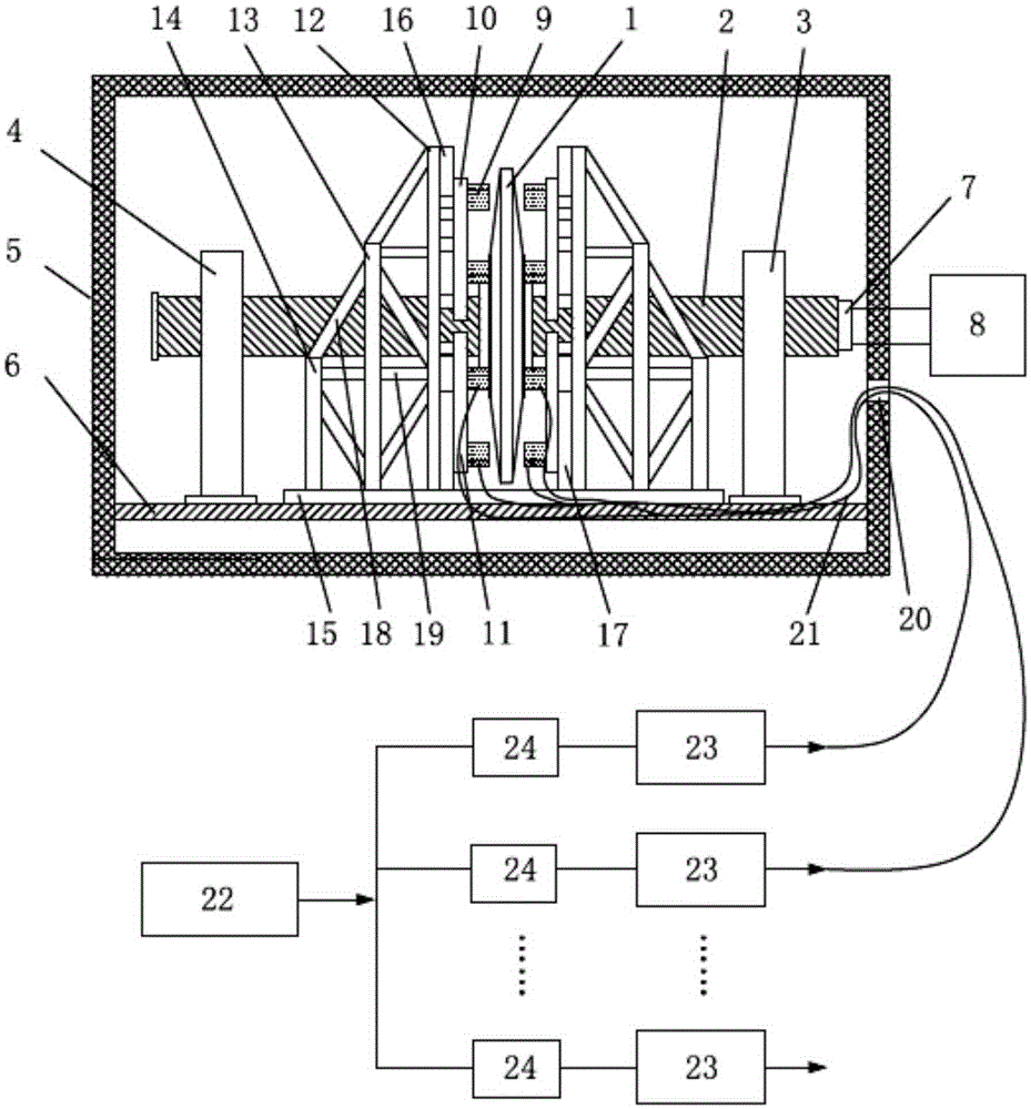
[0031] see figure 1 , an electromagnetic force excitation method for a high-speed rotating impeller of the present invention, including a vacuum cylinder 6, and a front swing frame 3 and a rear swing frame 4 installed in the vacuum cylinder 6, the impeller 1 to be tested together with the shaft 2 Installed on the front swing frame 3 and the rear swing frame 4, fixed on the swing frame track 5 in the vacuum cylinder 6, the front section of the shaft 2 is connected with the drive motor 8 outside the cylinder by a coupling 7.

[0032] One or more sets of electromagnetic exciters 9 are selected and arranged along the circumference of the impeller 1, and the brackets of the electromagnetic exciters are fixed on the track 5 of the pendulum frame inside the cylinder. A pair of electromagnetic exciters 9 are symmetrically arranged on the front and rear sides of the ...


PUM


Abstract

The invention discloses an electromagnetic harmonic wave exciting device for a high-speed rotating impeller. The electromagnetic harmonic wave exciting device comprises electromagnets, coils, installation boxes, electromagnetic exciter supports, power amplifiers and a signal generator. A sinusoidal signal is generated by use of the signal generator, passes through the power amplifiers and is then transmitted to electromagnetic exciters via a rectifier diode, and a sinusoidal excitation force is applied to the rotating impeller. A pair of electromagnetic exciters constitute a group and are symmetrically arranged at front and back of the impeller. A plurality of electromagnetic exciters are arranged along the circumference of the impeller and form circumferential sinusoidal excitation to the high-speed rotating impeller. The invention solves the problems of over temperature and insufficient excitation force due to that a conventional rotating impeller adopts a gas excitation manner, can meet sinusoidal excitation requirements of the impeller in a vibration test of the high-speed rotating impeller, and can adjust the amplitude of the sinusoidal excitation force.

Description

Technical field: [0001] The invention relates to a vibration test device for a high-speed rotating impeller, in particular to an electromagnetic harmonic excitation device for a high-speed rotating impeller. Background technique: [0002] Rotating impeller vibration test technology provides important test data basis for the design of impeller machinery such as steam turbines and gas turbines, and is one of the key technologies in the field of impeller design and test technology. With the development of impeller vibration and structural strength design technology and the deepening of impeller vibration safety research, higher requirements are put forward for the safety, reliability and accuracy of the rotating impeller vibration test system. [0003] Rotating impeller vibration measurement is divided into two types: contact type and non-contact type. The contact measurement method refers to pasting the vibration-picking strain gauge on the rotating impeller to directly obtai...

Claims


Application Information

Patent Timeline
Patent Type & Authority Applications(China)
IPC IPC(8): G01M7/02
Inventor 上官博肖俊峰高松于飞龙张永宁李园园南晴段静瑶
Owner XIAN THERMAL POWER RES INST CO LTD
Why Eureka
Try Eureka