Device for automatically controlling curing degree of optical fiber coating, and optical fiber production equipment

An automatic control device and optical fiber coating technology, which is applied to cladding optical fiber, glass optical fiber, optical waveguide and light guide, etc., can solve the problems of different curing degree of optical fiber outer coating, easy fluctuation of oxygen content, and inability to guarantee the adjustment range, etc. Achieve the effect of solving the curing of optical fiber coating, facilitating popularization and application, and ingenious overall design

Inactive Publication Date: 2016-01-20
NANJING WASIN FUJIKURA OPTICAL COMM LTD
View PDF6 Cites 11 Cited by
  • Summary
  • Abstract
  • Description
  • Claims
  • Application Information

AI Technical Summary

Problems solved by technology

At present, there is also a shutter with an adjustable inner aperture installed on the upper opening of the UV curing furnace, and the shutter is closed during the production process. This aperture is much smaller than the inherent size of the curing furnace to prevent air from entering the upper opening of the furnace body. Too much into the furnace, affected by the normal jitter of the optical fiber and the operation of personnel, it is impossible to guarantee that the adjustment range is the same every time
In addition, nitrogen gas is only injected into the upper port of the first UV curing furnace. In order to ensure the oxygen content of the curing furnace, under normal circumstances, the flow rate of nitrogen gas introduced is relatively large, which may easily cause fiber vibration and scrape the inner wall of the curing furnace to cause fiber breakage. , to sum up, under the same nitrogen flow rate, the oxygen content in the curing furnace tends to fluctuate, which easily causes the degree of curing of the outer coating of the optical fiber to be different and affects the quality of the optical fiber. Therefore, a new solution is urgently needed to solve the above technology question

Method used


Image

  • Device for automatically controlling curing degree of optical fiber coating, and optical fiber production equipment
  • Device for automatically controlling curing degree of optical fiber coating, and optical fiber production equipment
  • Device for automatically controlling curing degree of optical fiber coating, and optical fiber production equipment

Examples


Embodiment 1

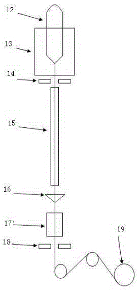
[0020] Example 1: See figure 1 , The optical fiber coating curing degree automatic control device, the automatic control device includes an ultraviolet curing oven 3, a connector, a gas flow sensor 6, an oxygen concentration measuring instrument 8, a controller 10, and a host computer 11, an ultraviolet curing oven 3 Connectors are provided on the upper and lower sides. The oxygen concentration measuring instrument 8 is connected to the controller 10 through a signal line, and the upper computer 11 is connected to the controller 10 through a control line; the connectors include a curing furnace upper connector 2 The lower port connector 4 of the curing furnace and the connector 5 with elastic sealing ring, wherein the upper port connector 2 of the curing furnace is arranged above the ultraviolet curing furnace 3 and connected to the nitrogen pipeline, and the nitrogen pipeline is equipped with a gas flow sensor 6. The gas flow sensor 6 is connected to the controller 10 through ...

Embodiment 2

[0021] Example 2: See figure 1 As an improvement of the present invention, the number of the ultraviolet curing oven is at least two, generally set to 6-10, according to the actual situation, use belt elasticity between two adjacent ultraviolet curing ovens The connector 5 of the sealing ring is connected to play a role of sealing, and a shutter 1 with adjustable inner diameter is connected to the upper mouth of the uppermost ultraviolet curing furnace 3 to prevent air from entering. The rest of the structure and advantages are exactly the same as the first embodiment.

Embodiment 3

[0022] Example 3: See figure 1 As an improvement of the present invention, the automatic control device further includes a gas flow adjustment device 9, which is arranged on the nitrogen pipeline and connected to the controller 10 through a signal line, wherein the nitrogen pipeline is arranged There is a regulating valve 7 to facilitate timely adjustment and control of the nitrogen content. The control method is as follows. After the bare fiber is coated, it enters the UV curing furnace for curing, and multiple oxygen concentration measuring instruments measure the oxygen concentration in the UV curing furnace connected in series to obtain the measured oxygen concentration. The signal is transmitted to the controller, and the controller compares and analyzes the collected oxygen concentration with the standard oxygen concentration set by the host computer. Through calculation, the nitrogen flow rate is automatically adjusted within a certain range. When the flow rate is adjust...


PUM


Abstract

The invention relates to a device for automatically controlling the curing degree of an optical fiber coating, and the device is characterized in that the device comprises an ultraviolet curing furnace, connectors, a gas flow sensor, an oxygen concentration measurement instrument, a controller, and an upper computer; the upper and lower sides of the ultraviolet curing furnace are provided with the connectors; the oxygen concentration measurement instrument is connected with the controller through a signal line; the upper computer is connected with the controller through a control line; the device achieves the curing degree of an optical fiber through the control of the internal oxygen concentration in the ultraviolet curing furnace, and simply and effectively solves problems of excessive curing, insufficient curing, pastiness and fiber jittering in a curing process of the optical fiber.

Description

technical field [0001] The invention relates to a control device, in particular to an automatic control device for the curing degree of optical fiber coating and optical fiber production equipment, belonging to the technical field of optical fiber production equipment. Background technique [0002] The optical fiber structure is the core, the cladding, the first layer of coating and the second layer of coating from the inside to the outside. Taking low water peak single-mode fiber as an example, the core is pure silica or silica glass doped with germanium dioxide, and the cladding is pure silica or silica doped with fluorine For glass, the coating layer is divided into one-layer coating and two-layer coating. The conventional coating is acrylic organic coating that can be cured by ultraviolet light. The reason why the structure of the optical fiber is so is that the bare fiber is very fragile and is easily damaged by direct exposure to the external environment. Therefore, t...

Claims


Application Information

Patent Timeline
Patent Type & Authority Applications(China)
IPC IPC(8): G02B6/44G02B6/02C03C25/50G05B19/04
CPCG02B6/4479C03C25/50G02B6/02395G02B6/4482G05B19/04
Inventor 周利佳王小泉姚晗
Owner NANJING WASIN FUJIKURA OPTICAL COMM LTD
Why Eureka
Try Eureka