Flexible OLED display panel
A display panel, flexible technology, applied in photovoltaic power generation, electrical components, circuits, etc., can solve the problems of barrier layer cracking, easy formation of aluminum salt, affecting the packaging effect, etc., to extend the path of water and oxygen intrusion, enhance the roll The effect of starting and enhancing the encapsulation effect
- Summary
- Abstract
- Description
- Claims
- Application Information
AI Technical Summary
Problems solved by technology
Method used
Image
Examples
no. 1 example
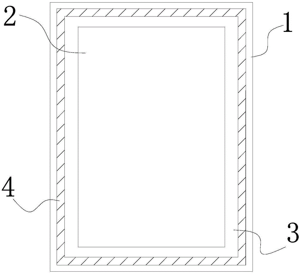
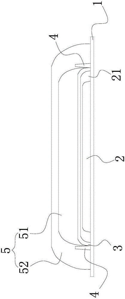
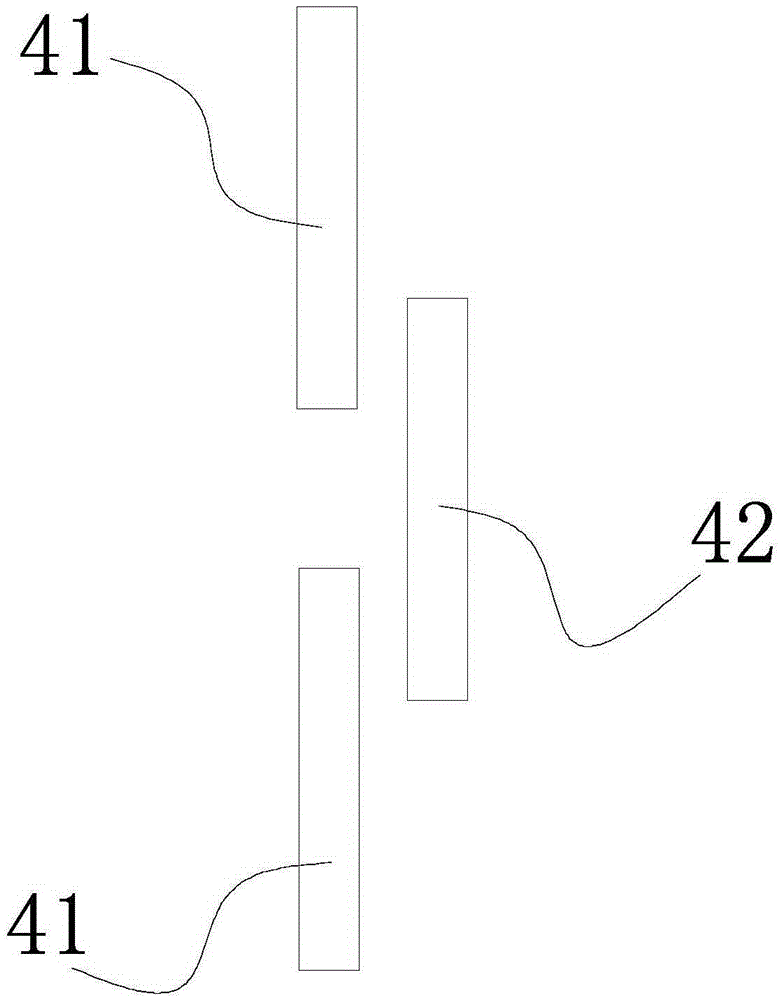
[0032] Please also see Figure 1 to Figure 3 , which respectively show the front view of the flexible OLED display panel of the first embodiment of the present invention, a schematic view of the longitudinal section structure, and a schematic view of the structure of the barrier layer. Among them, in order to clearly show the structure of the flexible OLED display panel, figure 1 The second encapsulation layer is omitted in , and the structure of the second encapsulation layer can be found in figure 2 . Such as figure 1 and figure 2 As shown, in the preferred embodiment of the present invention, the flexible OLED display panel includes: a flexible substrate 1 , an OLED device 2 , a first encapsulation layer 3 , a barrier layer 4 and a second encapsulation layer 5 .
[0033] Such as figure 2 As shown, the OLED device 2 is disposed on a flexible substrate 1 . The OLED device 2 at least includes a thin film transistor driving layer, an anode, a light emitting layer and a...
no. 2 example
[0042] See Figure 4 , which shows a schematic structural view of the barrier layer of the flexible OLED display panel according to the second embodiment of the present invention. with the above image 3 The difference from the first embodiment shown is that the barrier layer 4 is a rectangular overlapping structure. Specifically, with Figure 4 For example, in Figure 4 In the microscopic top view shown, the first blocking unit 41' is strip-shaped, while the second blocking unit 42' is U-shaped, and the two ends of each U-shaped second blocking unit 42' overlap two adjacent The first blocking unit 41'. The barrier layer shown in this embodiment can also have similar effects to that of the above-mentioned first embodiment, which will not be repeated here.
no. 3 example
[0044] See Figure 5 , which shows a schematic structural view of the barrier layer of the flexible OLED display panel according to the third embodiment of the present invention. with the above image 3 The difference from the first embodiment shown is that the barrier layer 4 is a U-shaped fastening structure. Specifically, with Figure 5 For example, in Figure 5 In the micro top view shown, both the first blocking unit 41 ″ and the second blocking unit 42 ″ are U-shaped. Wherein, the U-shaped first blocking unit 41 ″ is arranged opposite to the second blocking unit 42 ″. Such as Figure 5 As shown, the relative arrangement means that the orientations of the U-shaped openings are opposite. The barrier layer shown in this embodiment can also have similar effects to that of the above-mentioned first embodiment, which will not be repeated here.
PUM
 Abstract
Description
Claims
Application Information
 - R&D
- Intellectual Property
- Life Sciences
- Materials
- Tech Scout
- Unparalleled Data Quality
- Higher Quality Content
- 60% Fewer Hallucinations
Browse by: Latest US Patents, China's latest patents, Technical Efficacy Thesaurus, Application Domain, Technology Topic, Popular Technical Reports.
© 2025 PatSnap. All rights reserved.Legal|Privacy policy|Modern Slavery Act Transparency Statement|Sitemap|About US| Contact US: help@patsnap.com


