High pressure flow regulating valve stall protector

A technology of flow regulating valve and protector, applied in valve details, valve device, valve operation/release device, etc., to achieve the effect of low cost, stable operation and simple structure

Inactive Publication Date: 2017-10-20
NORTHEAST GASOLINEEUM UNIV
View PDF11 Cites 0 Cited by
  • Summary
  • Abstract
  • Description
  • Claims
  • Application Information

AI Technical Summary

Problems solved by technology

[0003] In order to solve the technical problems mentioned in the background technology, the present invention provides a high-pressure flow regulating valve stall protector. This kind of high-pressure flow regulating valve stall protector cleverly avoids the problem of directly using current to detect motor stall. The problem of misjudgment is caused, and the action state of the high-pressure flow regulating valve is used to judge whether there is scaling and whether the motor is blocked

Method used


Image

  • High pressure flow regulating valve stall protector
  • High pressure flow regulating valve stall protector
  • High pressure flow regulating valve stall protector

Examples


Embodiment Construction

[0015] The present invention will be further described below in conjunction with accompanying drawing:

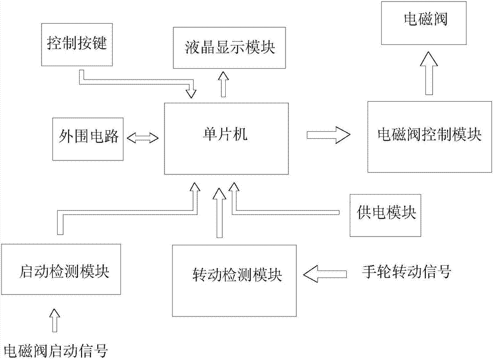
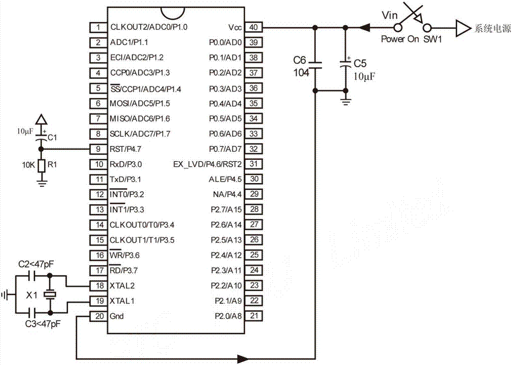
[0016] The purpose of this kind of high-pressure flow regulating valve locked-rotor protector is to disconnect the motor to protect the motor, control board and transmission rod of the high-pressure flow regulating valve when the regulating valve is fouled. It has a single-chip microcomputer and a control button coordinated with the single-chip microcomputer, a peripheral circuit, a liquid crystal display module and a power supply module. The single-chip microcomputer adopts STC12C5A60S2, and its peripheral circuit includes a reset circuit and a crystal oscillator circuit. The circuit diagram of the power supply module is as follows Image 6 As shown, it can be installed on the high-pressure flow regulating valve, and can obtain 220V AC mains power locally. In order to obtain the 5V DC required by the system, it is necessary to step down, rectify and stabilize the 220V AC....


PUM


Abstract

The utility model relates to a high-pressure flow regulating valve blocking protector. It mainly solves the problem that the traditional blocking protector working in the way of detecting the blocking current cannot be applied to the high-pressure flow regulating valve. It is characterized in that: the locked-rotor protector also includes a start-up detection module capable of detecting the start-up signal of the solenoid valve, a rotation detection module capable of detecting the rotation of the handwheel of the solenoid valve, and a solenoid valve control module capable of controlling the shut-off of the solenoid valve; wherein, the start-up The detection module is composed of a current detection diode group and an optocoupler; the rotation detection module is composed of a handwheel installed on the high-pressure flow regulating valve, a magnet fixed on the handwheel, and a reed switch sensor fixed on the high-pressure flow regulating valve body Composition; the solenoid valve control module is composed of 3 relay modules independent of each other, and each relay module controls the on-off of a solenoid valve motor control line; the control signal port of the solenoid valve control module is connected to the solenoid valve control of the single-chip microcomputer signal output.

Description

technical field [0001] The invention relates to a protection device for a high-pressure flowmeter used in the field of ternary compound displacement fluid to displace crude oil. Background technique [0002] Stall is the situation that affects the rotation of the motor caused by man-made or due to the limited driving capacity of the motor. When the motor rotates, the rotating magnetic field formed by the stator windings drives the rotor to rotate, and the magnetic field generated by the induced current in the rotor also induces a counter electromotive force in the stator windings, which is what we call inductive reactance, which prevents the motor from increasing the stator current. . If the motor is blocked, the above counter electromotive force disappears, and the motor is like an inductive element connected to the power supply, with only its own resistance and inductance, and the natural current will greatly increase. According to the size of the motor capacity and diff...

Claims


Application Information

Patent Timeline
Patent Type & Authority Patents(China)
IPC IPC(8): F16K31/04F16K37/00
CPCF16K31/046F16K37/0041
Inventor 魏立新王佳楠张宏奇叶卫东乔永娜张伟
Owner NORTHEAST GASOLINEEUM UNIV
Why Eureka
Try Eureka