Atmospheric plasma jet processing tool setting method

A plasma and jet technology, used in plasma welding equipment, metal processing, metal processing equipment, etc., to achieve the effects of low cost, commercialization, and simple structure

Active Publication Date: 2016-02-17
HARBIN INST OF TECH
View PDF5 Cites 5 Cited by
  • Summary
  • Abstract
  • Description
  • Claims
  • Application Information

AI Technical Summary

Problems solved by technology

[0005] The purpose of the present invention is to solve the tool setting problem of the atmospheric plasma jet, and also to meet the needs of the atmospheric plasma jet processing tool setting method that can accurately obtain the center of the plasma jet and complete the jet tool setting, and proposes an atmospheric plasma jet tool setting method. Plasma Jet Processing Tool Setting Device

Method used


Image

  • Atmospheric plasma jet processing tool setting method
  • Atmospheric plasma jet processing tool setting method
  • Atmospheric plasma jet processing tool setting method

Examples


specific Embodiment approach 1

[0037] Specific implementation mode 1, refer to Figure 1 to Figure 7 Describe this embodiment in detail, a kind of atmospheric plasma jet machining tool setting method described in this embodiment, this method is realized based on machine tool 5, machine tool 5 comprises machine tool control system 5-1 and plasma jet emission device 5-2 The machine tool control system 5-1 is used to record the moving distance of the workbench of the machine tool 5; the plasma jet emission device 5-2 is located above the workbench of the machine tool 5;

[0038] The method comprises the steps of:

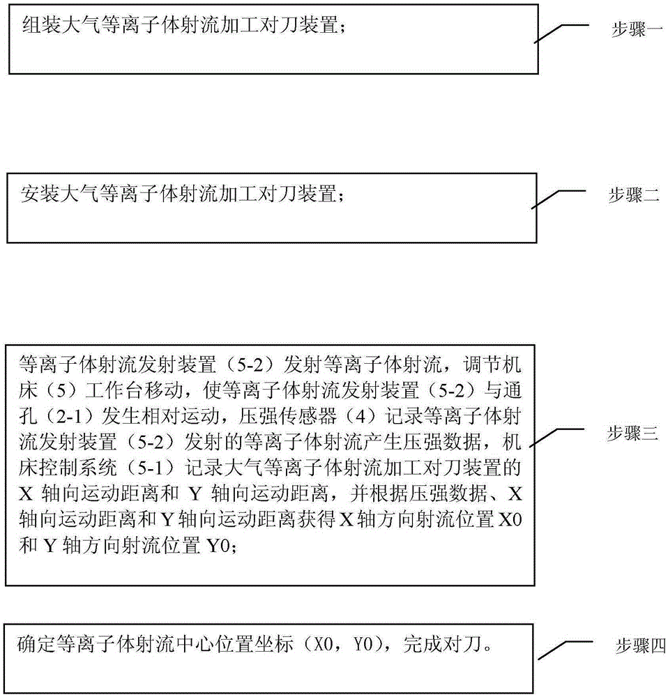
[0039] Step 1. Assembling the tool setting device for atmospheric plasma jet processing;

[0040] Step 2. Install the tool setting device for atmospheric plasma jet processing;

[0041] Step 3: The plasma jet emission device 5-2 emits the plasma jet, adjusts the movement of the workbench of the machine tool 5, so that the plasma jet emission device 5-2 moves relative to the through hole 2-1, and the...

specific Embodiment approach 2

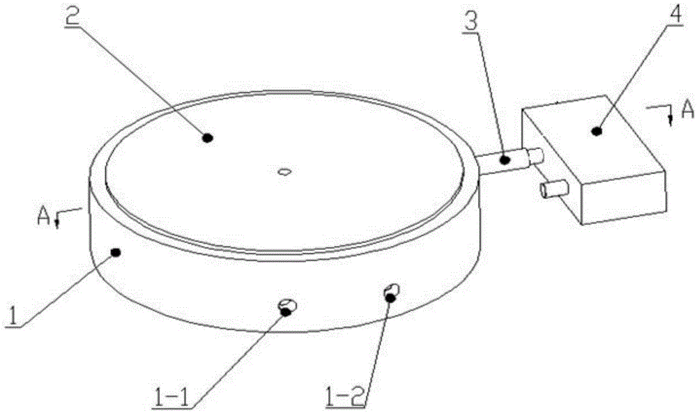
[0043] Specific implementation mode two, refer to Figure 2 to Figure 4 Describe this embodiment in detail. This embodiment is a further description of the tool setting method for atmospheric plasma jet processing described in Embodiment 1. In this embodiment, the tool setting device for atmospheric plasma jet processing includes a base 1 , fused silica sheet 2, connecting pipe 3 and pressure sensor 4;

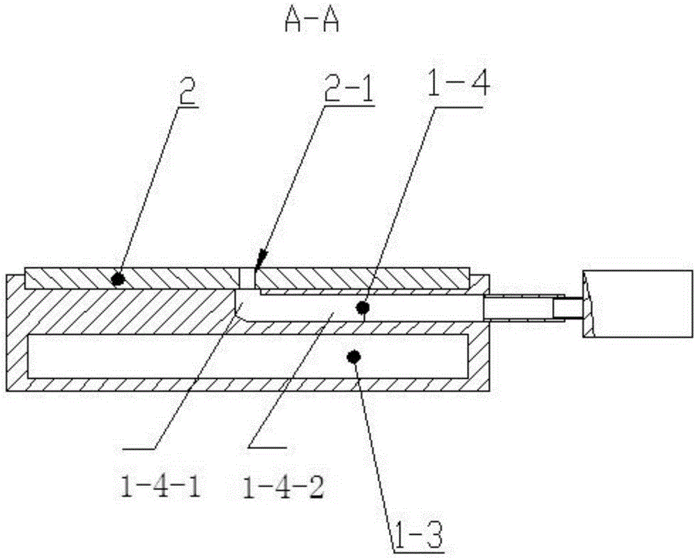
[0044] The upper surface of the base 1 is provided with a groove, the fused silica sheet 2 is fixedly arranged in the groove of the base 1, and the center of the fused silica sheet 2 is provided with a through hole 2-1;

[0045] The upper surface of the base 1 is provided with a channel 1-4, and the channel 1-4 includes a vertical channel 1-4-1 and a horizontal channel 1-4-2; a vertical channel 1-4-1 and a horizontal channel 1-4-2 Forming an L shape, one end of the vertical channel 1-4-1 communicates with the through hole 2-1, and one end of the horizontal channel 1-4-2 passe...

specific Embodiment approach 3

[0046] Specific Embodiment 3. This embodiment is a further description of the tool setting method for atmospheric plasma jet processing described in Embodiment 2. In this embodiment, an atmospheric plasma jet processing tool setting device is installed in step 2. The specific The installation method is:

[0047] The base 1 of the tool setting device for atmospheric plasma jet processing is fixed on the workbench of the machine tool 5, and the plasma jet emission device 5-2 is arranged above the through hole 2-1 of the fused silica sheet 2, and is located at Within the range of a circle with a diameter of 10 mm centered on the center of the through hole 2-1.


PUM

PropertyMeasurementUnit
diameteraaaaaaaaaa

Abstract

The invention discloses an atmospheric plasma jet processing tool setting method, relates to the field of precise optical processing, and solves the atmospheric plasma jet tool setting problem. The method comprises the following steps: 1) an atmospheric plasma jet processing tool setting device is assembled; 2) the atmospheric plasma jet processing tool setting device is installed; 3) a plasma jet emitting device emits plasma jets; a machine tool is adjusted to enable the plasma jet emitting device and a through hole to generate a relative motion; a pressure sensor records plasma jet generation pressure data; a machine tool control system records an X-axle moving distance and a Y-axle moving distance of the atmospheric plasma jet processing tool setting device; and an X-axle direction jet position X0 and a Y-axle direction jet position Y0 are obtained according to the pressure data, the X-axle moving distance and the Y-axle moving distance; and 4) the center position coordinate of the plasma jets is determined to finish the tool setting. The method is suitable for other places needing the tool setting.

Description

technical field [0001] The invention relates to the field of precision optical processing, in particular to a tool setting method for atmospheric plasma jet processing. Background technique [0002] Atmospheric plasma processing method is used to process optical lenses, the removal rate is high, and no sub-surface damage occurs. It belongs to a non-sub-surface damage processing method. This method can realize high-precision curved surface processing, and the atmospheric plasma processing method is used to process workpieces. , first of all to achieve accurate tool setting. [0003] When the workpiece is processed, the working gas of this method generates a plasma jet, which is sprayed onto the surface of the workpiece, thereby realizing processing. However, because the plasma jet is a kind of fluid, the traditional contact tool setting cannot be used, and because of the presence of various active particles, photon excitation, and specific spectral characteristics, the photo...

Claims


Application Information

Patent Timeline
Patent Type & Authority Applications(China)
IPC IPC(8): B23K10/00B23Q15/22B23Q17/22
CPCB23K10/00B23Q15/22B23Q17/2233
Inventor 王波王骏苏星吴言功张鹏
Owner HARBIN INST OF TECH
Why Eureka
Try Eureka