
DC/DC conversion circuit and power supply device

A conversion circuit and converter technology, applied in output power conversion devices, DC power input conversion to DC power output, electrical components, etc. , The effect of reducing voltage stress and improving reliability

Inactive Publication Date: 2016-02-17
SHENZHEN TIEON ENERGY TECH
View PDF7 Cites 9 Cited by
  • Summary
  • Abstract
  • Description
  • Claims
  • Application Information

AI Technical Summary

Problems solved by technology

[0005] The purpose of the present invention is to provide a DC / DC conversion circuit, which aims to solve the problems of large converter volume, low efficiency and poor reliability in the push-pull hard switching mode of DC / DC boost converter design

Method used


Image

  • DC/DC conversion circuit and power supply device
  • DC/DC conversion circuit and power supply device
  • DC/DC conversion circuit and power supply device

Examples


Embodiment 1

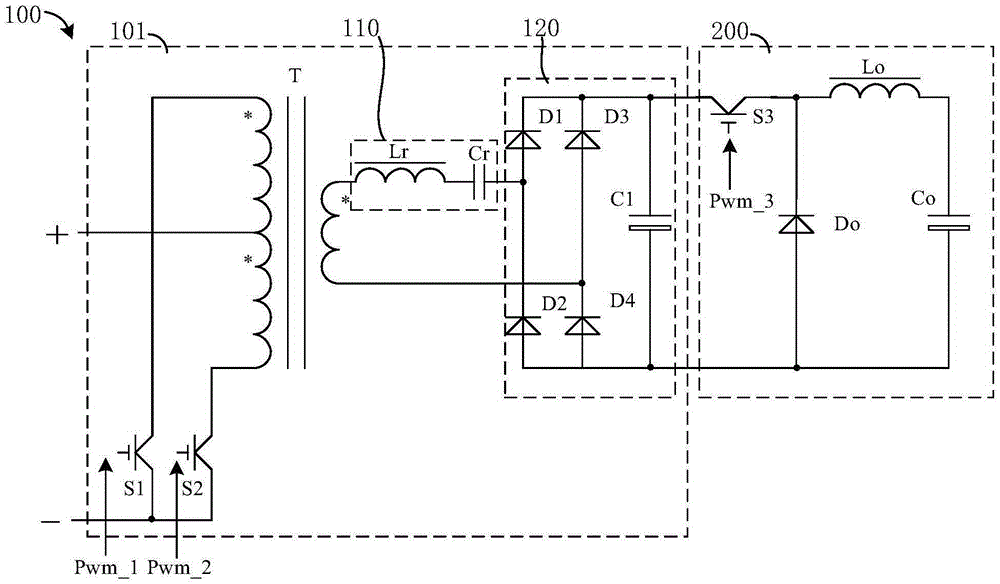
[0030] see figure 2 , in this embodiment, the DC / DC conversion circuit includes a push-pull converter 101 and a Buck conversion circuit, wherein the rectification module 120 of the push-pull converter 101 is a bridge rectification method.

Embodiment 2

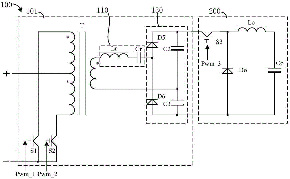
[0032] see image 3 , in this embodiment, the DC / DC conversion circuit includes a push-pull converter 101 and a Buck conversion circuit, wherein the rectification module 120 of the push-pull converter 101 is a voltage doubler rectification method.

[0033] In Embodiment 1 and Embodiment 2, the first drive signal Pwm_1 and the second drive signal Pwm_2 of the first switch tube S1 and the second switch tube S2 are complementary drives with a phase difference of 180°, and the preset maximum duty cycle, The dead time and the same fixed operating frequency as the resonant frequency of the resonant module 110, the soft start of the push-pull converter 101 can adopt the method of slowly releasing the driving duty cycle or gradually lowering the driving frequency from high to low to the steady-state frequency In this way, the push-pull output does not use any control, and the output of the entire converter is completely controlled by the closed-loop conversion circuit of the subsequen...

Embodiment 3

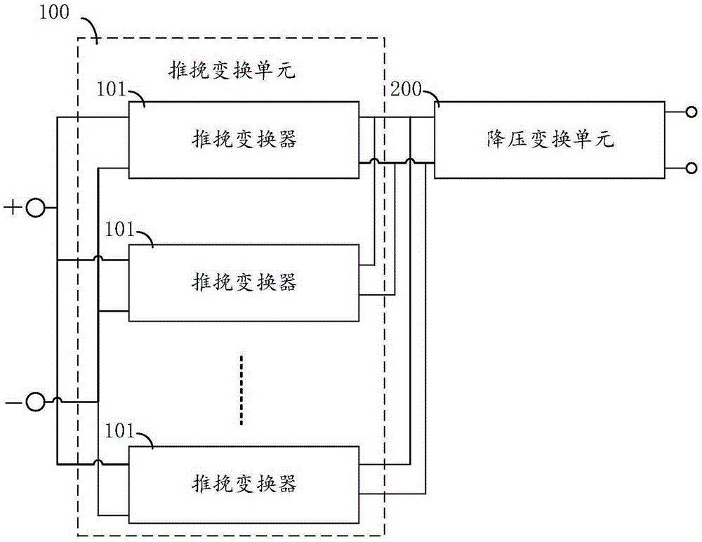
[0038] see Figure 4 , in this embodiment, the DC / DC conversion circuit includes two push-pull converters 101 and a Buck conversion circuit, and the two push-pull converters 101 are connected in parallel for input and output; the rectification module 120 of the push-pull converter 101 is a bridge rectifier The difference is that the rectification module 120 on each push-pull converter 101 includes a full-bridge rectifier, and the first filter capacitor C1 can only be provided on one of the rectification modules 120 .


PUM


Abstract

The invention relates to a DC / DC conversion circuit and a power supply device. The DC / DC conversion circuit comprises a push-pull conversion unit and a buck conversion unit being a buck conversion circuit. The push-pull conversion unit includes one or more parallel push-pull converters connected to a direct-current power supply; with open-loop control of soft switching, the push-pull converters works near a frequency of a resonance point and carry out outputting to the buck conversion circuit. The output voltage and / or current of the DC / DC conversion circuit are / is controlled by adjusting a drive signal of the buck circuit. At the front push-pull stage, the open-loop working mode of resonant soft switch series connection is employed and the output voltage and current of the whole converter are controlled by adjusting the back-stage buck conversion circuit, thereby improving the working frequency and efficiency of the converter and reducing the size and cost of the converter. Switching tubes and rectifier tubes work in a soft switch state, so that the voltage stress of the power tube is reduced and reliability of the converter design is improved.

Description

technical field [0001] The invention relates to switching power supply technology, in particular to a DC / DC conversion circuit and a power supply device. Background technique [0002] With the development of computer, communication technology, automobile industry and new energy technology, high-power power batteries have been used in electric tools, electric vehicles, aerospace and other fields. Bidirectional DC / DC conversion is currently a research hotspot in switching power supplies. Its application is more and more extensive, mainly including DC uninterruptible power supply system, aviation power supply system, vehicle power supply system such as electric vehicles, DC power amplifier and battery energy storage and other applications. Bidirectional DC / DC conversion includes boost conversion and buck conversion. , and the step-up conversion is a difficult point in the bidirectional DC / DC design. If the input voltage of the converter is low (such as only 12V when a single ba...

Claims


Application Information

Patent Timeline
IPC IPC(8): H02M3/337H02M3/156
Inventor 方耿
Owner SHENZHEN TIEON ENERGY TECH
Learn More