Heating and ventilation equipment temperature remote control system based on framework of Internet of Things
A remote control system and HVAC equipment technology, applied in the field of HVAC equipment temperature remote control system, can solve the problems of inability to integrate the Internet of Things technology and platform, inability to perform remote control and monitoring, and inability to adapt to technical requirements, etc., to achieve practicality Strong, easy to use, low cost effect
- Summary
- Abstract
- Description
- Claims
- Application Information
AI Technical Summary
Problems solved by technology
Method used
Image
Examples
Embodiment 1
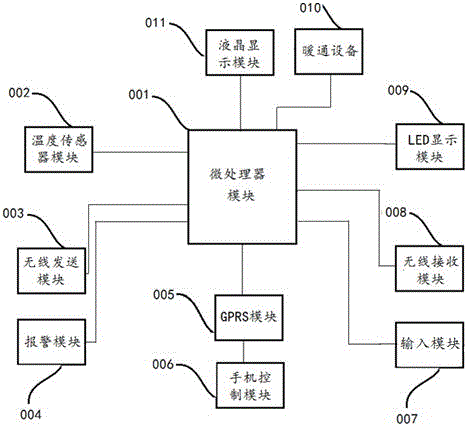
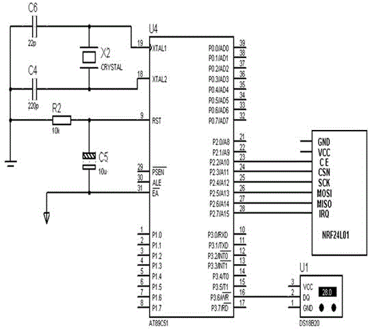
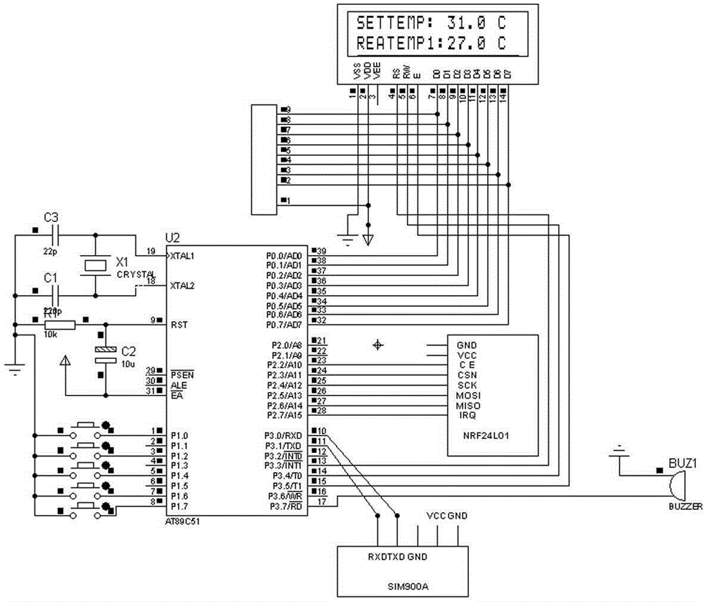
[0032] Such as figure 2 , 3 As shown, the HVAC equipment temperature remote control system based on the Internet of Things architecture includes sending-end hardware and receiving-end hardware. The sending-end hardware mainly includes: temperature sensor DS18B20, wireless transmitter NRF24L01, microprocessor module AT89S52, and microprocessor Module AT89S52 connects capacitors, resistors, and crystal oscillators in series or in parallel; the hardware at the receiving end mainly includes: wireless receiver NRF24L01, liquid crystal display LCD1602, LED light display, etc.
Embodiment 2
[0034] Such as Figure 4 As shown, the software design of the temperature sensor module 002 DS18B20 and the temperature measurement principle are strictly implemented in accordance with the single-bus protocol, and the accuracy of the communication data is ensured. The microprocessor module 001 writes and reads the data information in the DS18B20 according to the time sequence. Including initialization state, read one, read zero, write one, write zero and other operations. When the temperature sensor is set to zero, the corresponding response signal will be received, the data skips the serial number contained in the ROM, the temperature conversion module is started, and after the temperature conversion stops, the data is saved, and so on, to complete all operations.
Embodiment 3
[0036] Such as Figure 5 As shown, the initialization operation is performed first. The initialization steps mainly include setting the relevant ports of the microprocessor module I / O and SPI related registers to ensure that these two parts can communicate with nRF24L01. The radio frequency chip is adjusted by the SPI bus so that it can enter the precise working mode. When transmitting data, first set the working mode of nRF24L01 to transmit. Then write the target address TX-ADDR and data TX-PLD of the data to be transmitted by the sending end into the buffer zone of the wireless sensor module through the program diagram, and send the data after a period of time delay.
PUM
 Abstract
Description
Claims
Application Information
 - R&D
- Intellectual Property
- Life Sciences
- Materials
- Tech Scout
- Unparalleled Data Quality
- Higher Quality Content
- 60% Fewer Hallucinations
Browse by: Latest US Patents, China's latest patents, Technical Efficacy Thesaurus, Application Domain, Technology Topic, Popular Technical Reports.
© 2025 PatSnap. All rights reserved.Legal|Privacy policy|Modern Slavery Act Transparency Statement|Sitemap|About US| Contact US: help@patsnap.com


