Device for increasing superheat degree of smoke obtained after wet desulphurization and use method

A wet desulfurization and superheat technology, applied in separation methods, separation devices, chemical instruments and methods, etc., can solve the problems of easy blockage of heat exchangers, weak diffusion capacity and high failure rate, and achieve low resistance and increased superheat. , the effect of stable system operation

Active Publication Date: 2016-03-02
SHANDONG UNIV
View PDF4 Cites 4 Cited by
  • Summary
  • Abstract
  • Description
  • Claims
  • Application Information

AI Technical Summary

Problems solved by technology

Coal-fired power plants have used partition wall heat exchangers such as rotary heat exchangers (RGGH) or tubular heat exchangers (MGGH) to raise the dry bulb temperature of the wet flue gas after desulfurization to above 80°C to increase the superheat of the flue gas. To avoid rapid condensation of flue gas to solve the problems of chimney corrosion, "white smoke" and weak diffusion ability, but at present, due to the problems of easy blockage, large resistance and high failure rate of heat exchanger, it has been gradually eliminated and dismantled by power plants

Method used


Image

  • Device for increasing superheat degree of smoke obtained after wet desulphurization and use method

Examples


Embodiment 1

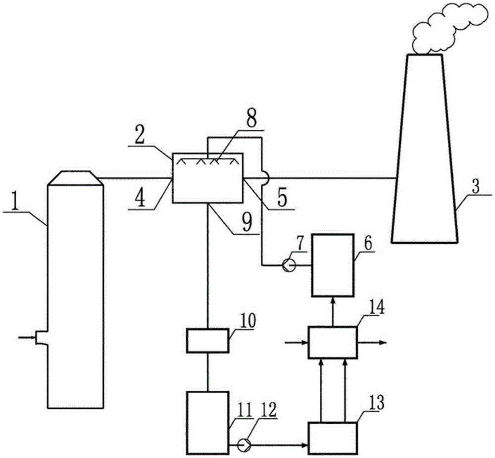
[0033] Such as figure 1 As shown, the saturated wet flue gas discharged from the desulfurization tower 1 with a temperature of about 50°C and a relative humidity of 100% enters the flue gas superheater 2 through the inlet 4 of the flue gas superheater, where the flue gas intersects with the absorption working medium Flow and direct contact for heat and mass exchange, part of the water vapor in the flue gas migrates to the absorption working fluid and releases heat, the moisture content of the flue gas decreases, the dew point temperature decreases, the dry bulb temperature increases, and the degree of superheat increases. Outlets 5 are combined and vented to atmosphere through chimney 3. Outside the flue gas superheater 2, there is a working medium pool 6 that delivers a set concentration of absorption working fluid to the flue gas superheater 2. The absorption working medium is input to the atomization nozzle 8 of the superheater through the absorption pump 7, and then passed...

Embodiment 2

[0037] The difference between this embodiment and embodiment 1 is:

[0038] A liquid receiving device is provided below the atomizing nozzle 8, and the liquid receiving device (a liquid receiving plate) includes a plurality of metal plates intersecting in the middle, and the middle part of each metal plate is lower than the two sides.

Embodiment 3

[0040] The difference between this embodiment and embodiment 1 is:

[0041] A filler is arranged below the atomizing nozzle 8 to increase the mass transfer area, reduce the volume of the equipment, and improve the dehumidification efficiency.


PUM


Abstract

The invention discloses a device for increasing the superheat degree of smoke obtained after wet desulphurization and a use method. The device comprises a smoke superheater. The smoke superheater comprises a container. A plurality of atomization nozzles are arranged in the container and connected with a working medium pool containing an absorption working medium of a certain concentration. The container is provided with a thin working medium outlet. A purifier, a thin working medium pool and a water-liquid separator are sequentially arranged between the thin working medium outlet and the working medium pool. The device and the use method have the advantages that vapor migrates to the absorption working medium from the smoke and releases heat through direct contact between the absorption working medium and the smoke, the dew point temperature of the smoke is decreased, temperature is increased, the superheat degree is increased, diffusion capability is enhanced, and thus the phenomenon that white smoke or chimney rain is formed at a chimney outlet is fundamentally avoided; no dividing wall type heat exchange device is needed, the smoke and the absorption working medium make direct contact for heat transfer and mass transfer, efficiency is high, resistance is small, and the parameters of the chimney outlet can be regulated as needed.

Description

technical field [0001] The invention relates to the technical field of flue gas latent heat, in particular to a device for increasing the superheat of flue gas after wet desulfurization, which integrates the functions of demisting, recovering water vapor in flue gas, and eliminating "white smoke" and "chimney rain". and how to use it. Background technique [0002] Most coal-fired power plants in my country use wet flue gas desulfurization processes, including limestone-gypsum method, ammonia method, and seawater desulfurization processes. During this process, the SO in the flue gas 2 Absorbed by the absorption liquid to achieve the removal of SO 2 the goal of. [0003] In the process of wet desulfurization, the flue gas is cooled and humidified in the desulfurization tower. A large amount of water absorbs heat and evaporates. The saturated wet flue gas at 50°C and 100% relative humidity is discharged through the wet chimney. Due to the temperature difference between the w...

Claims


Application Information

Patent Timeline
Patent Type & Authority Applications(China)
IPC IPC(8): B01D53/14B01D53/18B01D47/06B01D47/05B01D47/14F23J15/06
CPCB01D47/05B01D47/06B01D47/14B01D53/1425B01D53/1493B01D53/18B01D2247/04B01D2252/10F23J15/06Y02E20/30
Inventor 董勇吕扬崔琳
Owner SHANDONG UNIV
Why Eureka
Try Eureka