Electromagnetic ultrasonic probe

An electromagnetic ultrasonic and magnetic shoe technology, which is applied in the direction of material analysis, measuring devices, and instruments using sound waves/ultrasonic waves/infrasonic waves. The effect of enhanced anti-interference ability and simple operation

Active Publication Date: 2016-03-02
HEBEI UNIV OF TECH
View PDF11 Cites 5 Cited by
  • Summary
  • Abstract
  • Description
  • Claims
  • Application Information

AI Technical Summary

Problems solved by technology

By integrating the preamplifier module inside the electromagnetic ultrasonic probe, the electromagnetic ultrasonic probe can significantly increase the amplitude of the electromagnetic ultrasonic signal output by the electromagnetic ultrasonic probe, and overcome the low conversion efficiency of the electromagnetic ultrasonic signal caused by the signal transmission process, which is easily affected by

Method used


Image

  • Electromagnetic ultrasonic probe
  • Electromagnetic ultrasonic probe
  • Electromagnetic ultrasonic probe

Examples


Embodiment 1

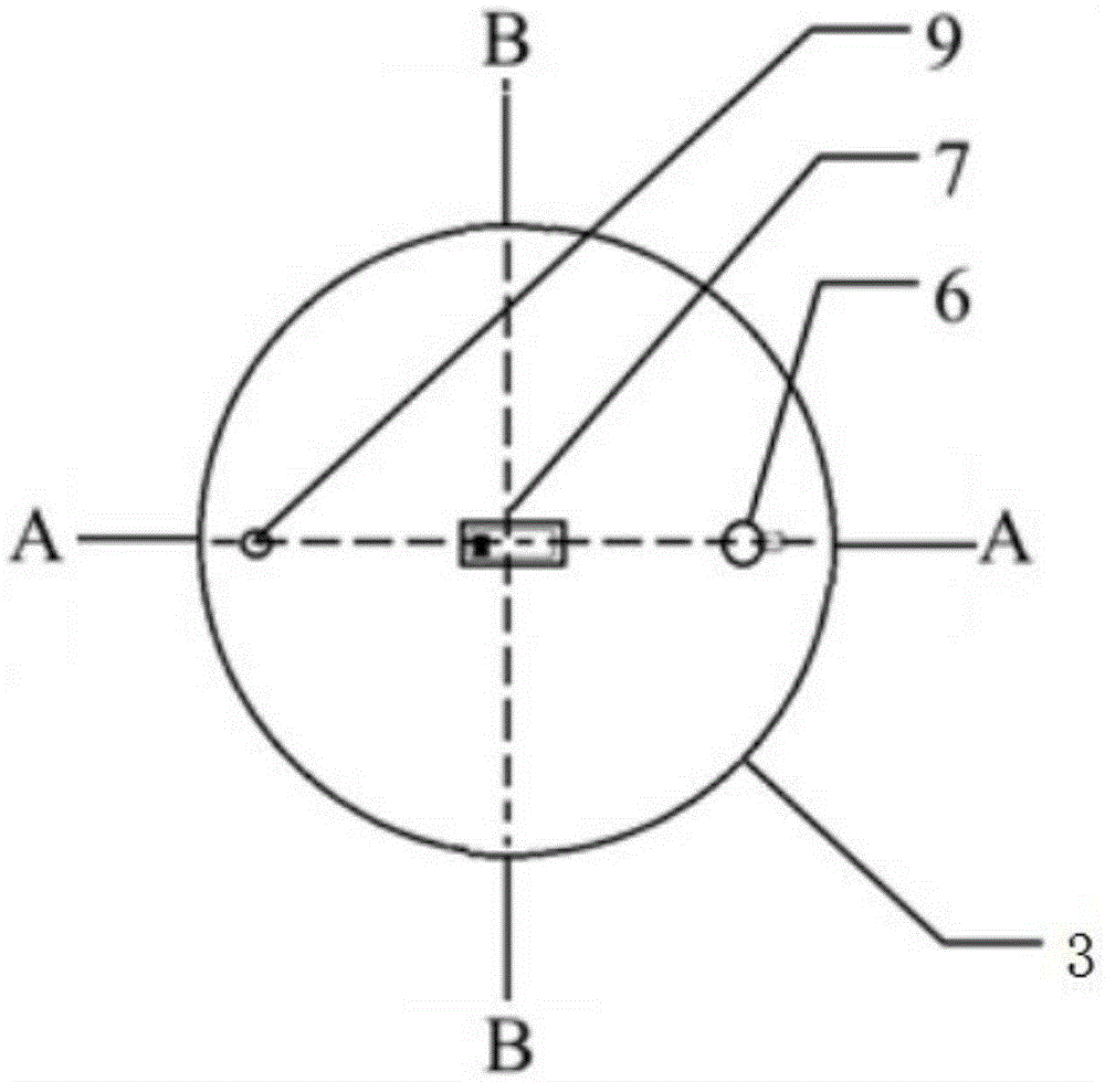
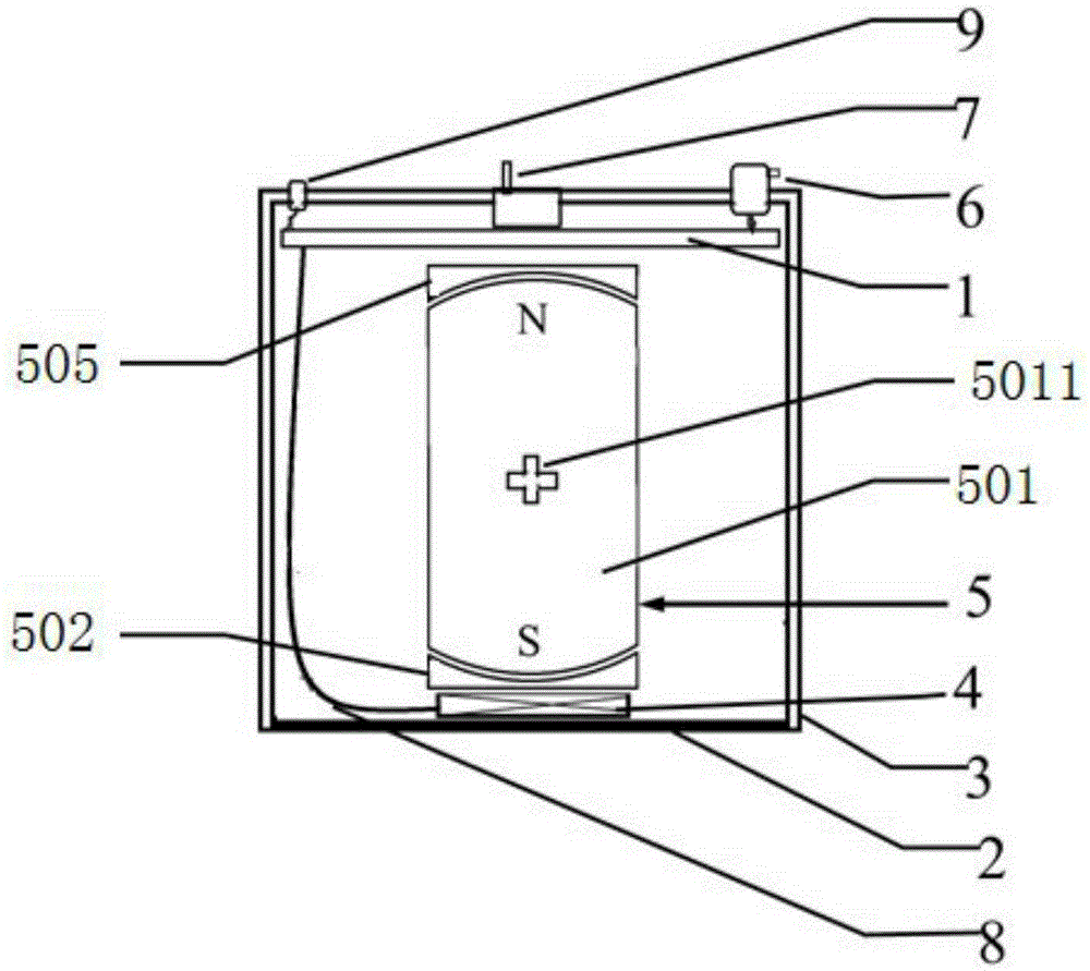
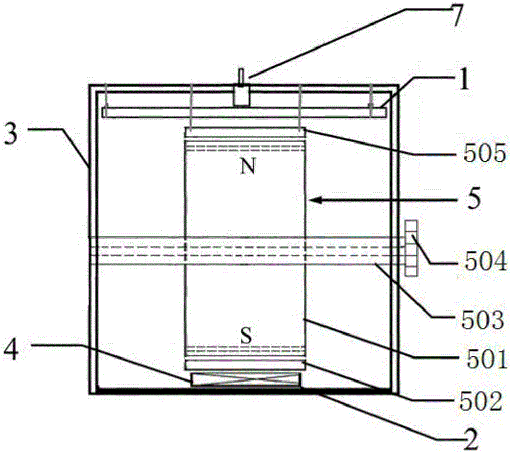
[0035] This embodiment adopts the electromagnetic ultrasonic probe of the above-mentioned connection mode, wherein the permanent magnet 501 is made of NdFeB material, the second arc-shaped magnetic shoe 505 is made of low-carbon steel material, and the shell 3 is made of magnetically conductive steel material. For the connection method of the primary amplifier circuit and the secondary amplifier circuit, see Figure 4 and Figure 5 .

[0036] Implement 170V square wave excitation on the piezoelectric probe 11 for 7 consecutive cycles with a frequency of 1MHz. The receiving coil 4 adopts a zigzag coil, and the toggle switch 7 is moved to the first gear. At this time, the gain of the preamplifier module 1 is 20dB. With respect to the ultrasonic signal of the microvolt level, this embodiment realizes the adjustment of the 10-fold gain of the received ultrasonic signal by calculating the function of the circuit, and the output voltage of the receiving coil 4 obtained is shown in ...

Embodiment 2

[0038] In this embodiment, the electromagnetic ultrasonic probe described in Embodiment 1 is adopted, and the piezoelectric probe is excited by a 170V square wave for 7 consecutive cycles with a frequency of 1 MHz. The receiving coil 4 adopts a folding coil, and the toggle switch 7 is moved to the second position. At this time, the gain of the preamplifier module is 40dB. Compared with the ultrasonic signal at the microvolt level, this embodiment realizes the adjustment of the 100-fold gain of the received ultrasonic signal through the function of the circuit. The output voltage of the receiving coil 4 is as shown in the figure As shown in Fig. 7(b), the ultrasonic signal directly emitted by the piezoelectric probe (the first signal in Fig. 7(b)) and the ultrasonic signal reflected by the crack can be clearly identified and distinguished from the collected signal (the second signal in Figure 7(b)), the signal amplitude is 10 times larger than the signal amplitude of the first g...

Embodiment 3

[0040] In this embodiment, the electromagnetic ultrasonic probe described in Embodiment 1 is used, and the piezoelectric probe 11 is excited by a 170V square wave for 7 consecutive cycles with a frequency of 1 MHz. The receiving coil adopts a folding coil, and the toggle switch is moved to the third position. At this time, the gain of the preamplifier module is 60dB. Compared with the ultrasonic signal at the microvolt level, this embodiment realizes the adjustment of the 1000-fold gain of the received ultrasonic signal through the function of the circuit. The output voltage of the receiving coil is shown in Figure 7(c). It is shown that the ultrasonic signal directly emitted by the piezoelectric probe (the first signal in Fig. 7(c)) and the ultrasonic signal reflected by the crack (Fig. 7(c) The second signal in the middle), the signal amplitude is about 100 times higher than the signal amplitude of the first gear.


PUM


Abstract

The invention relates to an electromagnetic ultrasonic probe which is characterized by comprising a preposition amplifying module, an isolating layer, a shell, a receiving coil and a permanent magnetic device; the top face of the shell is provided with a poking switch, a power line interface and a BNC connector, the inner side of the bottom face of the shell is provided with the isolating layer, the centers of the two side faces of the shell are provided with holes respectively, the preposition amplifying module is located in the shell and fixed to the inner side of the top face of the shell through a screw, and the receiving coil is pasted to the isolation layer; the receiving coil is connected with the input end of the preposition amplifying module through a signal line, the output end of the preposition amplifying module is connected with the BNC connector fixed to the shell, the poking switch controls the gear position of the preposition amplifying module, and the power line connector is connected with an external power source; the permanent magnetic device comprises a permanent magnetic body, a first curved magnetic boot, a second curved magnetic boot, a cross coupling and a mechanical knob, a permanent magnetic device is located between the two curved magnetic boots, and the middle of the permanent magnetic body is provided with a cross hole groove.

Description

technical field [0001] The invention belongs to the technical field of industrial measurement, and in particular relates to an electromagnetic ultrasonic probe. Background technique [0002] In recent years, non-destructive testing technology has played an increasingly important role in the detection and evaluation of industrial equipment reliability and safety. Due to the characteristics of non-contact, no coupling agent and good repeatability, electromagnetic ultrasonic testing technology has great application prospects in the fields of non-destructive testing such as steel, aerospace and railway transportation. [0003] Compared with traditional piezoelectric detection, electromagnetic ultrasonic energy conversion efficiency is low, and the collected electromagnetic ultrasonic signal is weak, even down to microvolt level. the effect of noise. Especially in industrial applications, it is easy to cause false detection and missed detection due to external noise, which limi...

Claims


Application Information

Patent Timeline
IPC IPC(8): G01N29/24
CPCG01N29/24
Inventor 张闯刘素贞杨蒙杨庆新
Owner HEBEI UNIV OF TECH
Why Eureka
Try Eureka