
Pneumatic steady flame center staged combustor

A central grading and combustion chamber technology, which is applied in combustion chambers, continuous combustion chambers, combustion methods, etc., can solve problems such as complex mechanical structure, achieve simple geometric configuration, improve ignition performance, processing technology and simple mechanical installation.

Inactive Publication Date: 2016-03-16
BEIHANG UNIV
View PDF7 Cites 9 Cited by
  • Summary
  • Abstract
  • Description
  • Claims
  • Application Information

AI Technical Summary

Problems solved by technology

[0003] At present, the staged combustion chamber and the main combustion stage nozzle mainly use air atomizing nozzles, which use swirling air to atomize the fuel. The mechanical structure of this type of nozzle is relatively complicated.

Method used


Image

  • Pneumatic steady flame center staged combustor
  • Pneumatic steady flame center staged combustor

Examples


Embodiment Construction

[0025] The present invention will be described in detail below in conjunction with the accompanying drawings and specific embodiments.

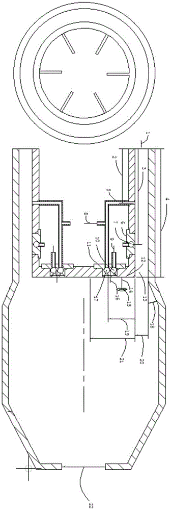
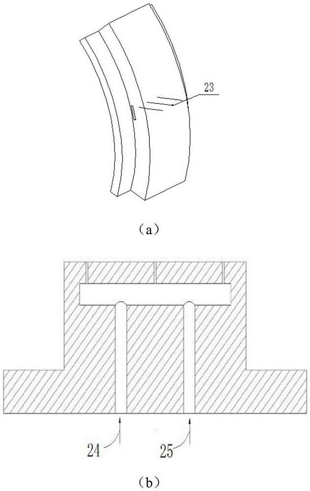
[0026] Such as figure 1 As shown, the embodiment of the present invention is an aerodynamic flame stabilizing center staged combustor, which is mainly composed of main combustion stage flow channel 13, back step pre-combustion stage 12, main combustion stage direct injection nozzle 6, pre-combustion stage airflow induced trapped vortex nozzle 11 Constitute with spark igniter 15. The direct injection nozzle 6 of the main combustion stage is composed of a No. 1 oil inlet 24 , a No. 2 oil inlet 25 , an oil collecting chamber 7 and an injection hole 23 . The pre-combustion level airflow induced trapped vortex nozzle 11 has two independent gas collection chambers and two rows of nozzle holes, namely the nitrogen gas collection chamber 10 and the premix gas collection chamber 17 , and the nitrogen gas injection holes 26 and the premix gas injectio...


PUM


Abstract

The invention discloses a pneumatic steady flame center staged combustor. A main combustion stage annular direct-injection type nozzle consists of a first oil inlet, a second oil inlet, an oil collecting cavity and an injection hole; a pre-combustion stage nozzle is provided with two independent gas collecting chambers and two rows of spray orifices which respectively spray nitrogen and methane / air premixed gas; and after entering an inlet of an annular combustion chamber, air is distributed into different flows which respectively enter a main combustion stage annular flow path and a pre-combustion stage pre-mixing channel. The main combustion stage direct-injection type nozzle transversely sprays liquid fuel oil into the main combustion stage annular flow path, and then the liquid fuel oil is mixed with main combustion stage air flow. The methane / air premixed gas and the nitrogen are obliquely and upwards sprayed into a backward-facing step pre-combustion stage by pre-combustion stage air flow; an electric spark igniter is positioned on a methane / air premixed gas injection track, and ignition starting of the pre-combustion stage is realized; and then high-temperature fuel gas of the pre-combustion stage ignites a main combustion stage. Mechanical components of the pneumatic steady flame center staged combustor are simple, stable and reliable in structure, and the liquid fuel oil can be efficiently and stably combusted in a wider incoming flow working condition range.

Description

technical field [0001] The invention relates to the technical field of staged combustion chambers, in particular to an aerodynamic flame stabilizing center staged combustion chamber. Background technique [0002] With the continuous development of aero-engine technology, while the performance of the engine is improving, the requirements for the pollution emission of the engine are becoming more and more stringent. The staged combustion chamber is an important mode of the low-pollution combustion chamber. The staged combustion chamber can change the distribution ratio of fuel or air according to the change of engine power, so that it can be burned at the most suitable fuel-air ratio, thereby reducing pollutant emissions to the greatest extent. [0003] At present, the staged combustion chamber and the main combustion stage nozzle mainly use air atomizing nozzles, which use swirling air to atomize the fuel. The mechanical structure of this type of nozzle is relatively complica...

Claims


Application Information

Patent Timeline
Patent Type & Authority Applications(China)
IPC IPC(8): F23R3/28F23R3/02
Inventor 林宇震靳勇张弛赵永胜
Owner BEIHANG UNIV
Learn More