Solid waste two-stage pyrolysis gasification system based on fluidized bed and moving bed

A solid waste, pyrolysis gasification technology, applied in gasification process, granular/powdered fuel gasification, combustible gas production, etc., to achieve good solid-solid contact, uniform heating, and high thermal efficiency

Active Publication Date: 2016-03-23
代建军 +1
View PDF5 Cites 16 Cited by
  • Summary
  • Abstract
  • Description
  • Claims
  • Application Information

AI Technical Summary

Problems solved by technology

The incineration of garbage and other wastes is easy to produce pollutants such as dioxins, which has been plagued by the waste treatment industry
At present, there is no technology and device that effectively combines indirect heating pyrolysis technology and microwave heating at home and abroad.

Method used


Image

  • Solid waste two-stage pyrolysis gasification system based on fluidized bed and moving bed
  • Solid waste two-stage pyrolysis gasification system based on fluidized bed and moving bed

Examples


Embodiment 1

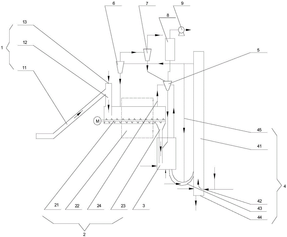
[0027] See figure 1, the system includes a solid waste feed system 1 , a pyrolyzer 2 , a biochar collector 3 , a circulating fluidized bed gasifier 4 , a gasifier cyclone separator and a cyclone separation reactor 5 connected in sequence. The solid waste feeding system 1 includes a conveyor 11 and a feeding downcomer 12 , the conveyor 11 communicates with the middle and upper part of the feeding downcomer 12 , and can transport solid waste into the feeding downcomer 12 . The feed downcomer 12 is located above the pyrolyzer 2, and its top is a supplementary bed material inlet 13. The feed downcomer 12 extends deep into the interior of the pyrolyzer 2 until it is above the screw, and there is a certain distance between the screw and the screw. . The material in the feed downcomer 12 provides a material seal.

[0028] The pyrolyzer 2 comprises a pyrolyzer shell, which has a horizontal screw reactor 21 inside and a microwave heater 22 outside. The top of the tail of the pyrolyze...

Embodiment 2

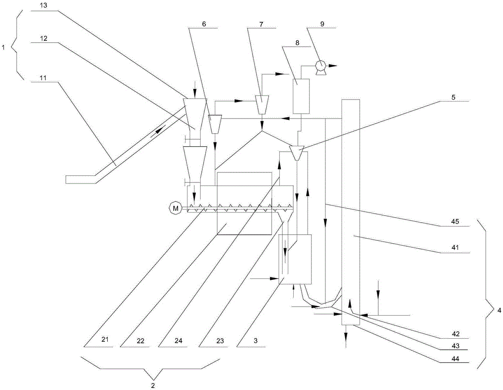
[0034] See figure 2 , The difference between this embodiment and Embodiment 1 is: the feed downcomer is a lock hopper system. The feeding downpipe 12 is a two-section pipe structure with upper and lower sections. A valve is respectively installed at the bottom of the two sections of pipe. The two valves are alternately opened and closed to ensure the sealing of the reaction system and to realize continuous feeding. The bottom of the secondary cyclone separator 7 of the gasifier is respectively connected to the discharge pipe at the lower end of the cyclone separation reactor 5 and the primary cyclone separator 6 of the gasifier. Other system components are the same as in Embodiment 1.

Embodiment 3

[0036] The difference between this embodiment and embodiment 1 is: the cyclone separation reactor 5 is arranged inside the pyrolyzer 2; the screw material of the pyrolyzer 2 is ceramic. Other system components are the same as in Embodiment 1.


PUM


Abstract

The invention relates to a solid waste two-stage pyrolysis gasification system based on a fluidized bed and a moving bed. The system comprises a circulating fluidized bed vaporizer and a secondary cyclone separator thereof, a pyrolyzer and a cyclone separation type reactor thereof, a charcoal collector, a solid waste feed system and the like. The circulating fluidized bed vaporizer and the pyrolyzer of the moving bed are used to realize two-stage pyrolysis gasification, and the cyclone separation type reactor is used to sufficiently mix hot bed materials and pyrolysis gas, thus greatly promoting tar splitting and gas purification. Through optimally designing the vaporizer and pyrolyzer structure form, mixing different bed materials for use, improving a bed material circulation flow system and gas solid mixing level, and improving the feed system, synthesis gas and the pyrolysis gas are produced simultaneously, the overall pyrolysis gasification efficiency and a pyrolysis gas heat value are greatly improved and increased, tar content in the synthesis gas and the pyrolysis gas is reduced, and the synthesis gas and the pyrolysis gas do not contain pollutants such as dioxin, thus effectively preparing the high-quality clean pyrolysis gas and synthesis gas.

Description

technical field [0001] The invention relates to a solid waste pyrolysis gasification device, in particular to a two-stage solid waste pyrolysis gasification system based on a fluidized bed and a moving bed. Background technique [0002] Energy is the basis for the survival and development of modern society. China's current energy supply situation is severe and environmental problems are serious. The development of clean and renewable energy has become an urgent issue. Agricultural, forestry and garbage and other wastes are low-carbon energy sources. China has abundant resources of agricultural, forestry and garbage and other wastes. Its research and development, promotion and popularization will help reduce pollutant emissions and improve the ecological environment. Industrial sludge is also a solid waste that needs to be treated urgently, and pyrolysis gasification will be an effective and promising treatment method. The incineration of garbage and other wastes is easy to ...

Claims


Application Information

Patent Timeline
IPC IPC(8): C10J3/60C10J3/56C10J3/62C10J3/84
CPCC10J3/56C10J3/60C10J3/62C10J3/84C10J2300/0946C10J2300/0956C10J2300/1603
Inventor 代建军李晶
Owner 代建军
Why Eureka
Try Eureka