Common-path digital holographic microscopic device and method based on optical grating defocusing

A digital holographic microscope and grating technology, applied in the direction of optical devices, measuring devices, instruments, etc., can solve the problems that the detection window utilization rate is only 1/2, the size of the object to be measured is limited, etc., and meet the system positioning complexity requirements Low, easy to determine, and simple mapping relationship

Active Publication Date: 2016-03-23
HARBIN ENG UNIV
View PDF6 Cites 24 Cited by
  • Summary
  • Abstract
  • Description
  • Claims
  • Application Information

AI Technical Summary

Problems solved by technology

[0004] In order to improve the anti-interference ability of the system and simplify the system structure, the inventor proposed a series of dual-window common-path interference detection methods and devices based on grating defocus, such as ZL201210424239.2 "Common-optical-path interference detection device and method based on synchronous carrier frequency phase shifting" ", the incident surface of the 4f optical system is divided into two windows, one of which is used to place the object to be measured, and the other is used as a reference window, and a grating is placed at the frequency domain defocus of the 4f optical system to introduce the carrier, thereby obtaining carrier holography Figure, but because the incident surface is divided into two windows, not only the utilization rate of the detection window is only 1 / 2, but also the size of the object to be measured is limited

Method used


Image

  • Common-path digital holographic microscopic device and method based on optical grating defocusing
  • Common-path digital holographic microscopic device and method based on optical grating defocusing
  • Common-path digital holographic microscopic device and method based on optical grating defocusing

Examples


Embodiment Construction

[0033] The present invention will be described in further detail below in conjunction with the accompanying drawings.

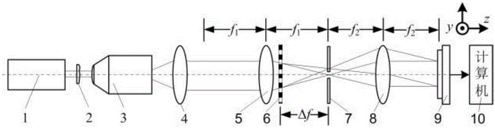
[0034] The purpose of the present invention is to address the deficiencies of the prior art, combining grating defocus spectroscopic technology and hole array filtering technology, and propose a co-channel digital holographic microscopic device and method based on grating defocus.

[0035] The invention belongs to the field of digital holographic detection, in particular to a co-channel digital holographic microscopic device and method based on grating defocus. A co-channel digital holographic microscope device light source based on grating defocus, a microscope objective lens correction objective lens, a first lens, a one-dimensional periodic grating, an aperture array, a second lens, an image sensor and a computer. The invention is simple and easy to operate, easy to adjust, and the size of the object to be measured is not limited, and the field of view of ...


PUM


Abstract

The invention discloses a common-path digital holographic microscopic device and method based on optical grating defocusing. The device comprises a light source, a to-be-detected object, a microscopic object lens, a correction object lens, a first lens, a second lens, an image sensor, and a computer. The device also comprises a one-dimensional periodic optical grating and a hole array. Light emitted by the light source passes through the to-be-detected object, the microscopic object lens and the correction object lens to come to the first lens. An outgoing beam, formed after the first lens converges the light, passes through the one-dimensional periodic optical grating to be divided into zero-level diffracted light and +1-level diffracted light, and is filtered by the hole array to form reference light and object light. The reference light and object light pass through the second lens to be converged into a light beam, and the light beam is received by a light receiving surface of the image sensor. An image signal output end of the image sensor is connected with an image signal input end of the computer. The device is simple and practicable, and is convenient to adjust. Moreover, the size of a to-be-detected object is not limited, and the view field of a detection window is used fully. The device can greatly reduce the complexity in determining a system carrier frequency, and improves the phase recovery algorithm efficiency.

Description

technical field [0001] The invention belongs to the field of digital holographic detection, in particular to a co-channel digital holographic microscopic device and method based on grating defocus. Background technique [0002] Based on the principle of interference, digital holographic detection technology uses image sensors such as CCD or CMOS to record holographic (interferometric) images, and uses computers to digitally reproduce the surface topography of objects. The extremely important test and analysis methods are widely used in measurement fields such as biomedicine, micro-nano devices, and optical micro-processing. The traditional digital holography system uses Michelson, Mach-Zehnder and other separate optical path interference. The reference beam and measurement beam pass through different paths, which are easily affected by external vibrations and temperature fluctuations, and have poor anti-interference ability. Compared with the separate optical path structure...

Claims


Application Information

Patent Timeline
Patent Type & Authority Applications(China)
IPC IPC(8): G01B9/021
CPCG01B9/027
Inventor 单明广邓平科钟志张雅彬刁鸣
Owner HARBIN ENG UNIV
Why Eureka
Try Eureka