Gas storage tank
A gas storage tank, liquefied gas technology, applied in gas/liquid distribution and storage, fixed-capacity gas storage tanks, pressure vessels, etc., can solve the problems of increasing transportation costs, increasing the space occupied by the weight of storage tanks, etc.
- Summary
- Abstract
- Description
- Claims
- Application Information
AI Technical Summary
Problems solved by technology
Method used
Image
Examples
Embodiment 1
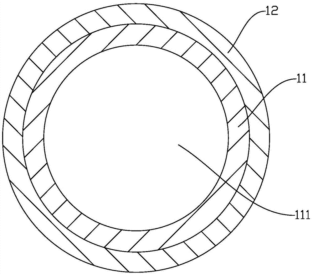
[0058] like figure 1 As shown, the gas storage tank includes a tank body 1 . The tank body 1 includes an inner container 11 . The radial section of the liner 11 is circular. The inner tank 11 is provided with a cavity 111 for storing liquefied gas. The inner tank 11 is made of pure metal, alloy or resin, which prevents the leakage of liquefied gas in the cavity 111 and plays a sealing role. The outer surface of the liner 11 is covered with a layer of first fiber reinforced material layer 12 . The first fiber-reinforced material layer 12 is formed by heating and curing the first fiber-reinforced material wire or the first fiber-reinforced material strip wrapped around the outer surface of the inner container 11 .
[0059] The first fiber-reinforced material layer 12 is a first fiber-reinforced resin layer, and the first fiber-reinforced resin layer includes first fibers and a first resin. Wherein, the first fiber is selected from glass fiber, carbon fiber, metal fiber, bor...
Embodiment 2
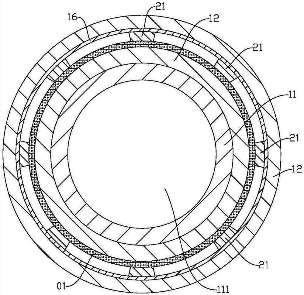
[0063] like figure 2 As shown, the gas storage tank includes a tank body 1 . The tank body 1 includes an inner container 11 . The radial section of the liner 11 is circular. The inner tank 11 is provided with a cavity 111 for storing liquefied gas. The inner tank 11 is made of pure metal, alloy or resin, which prevents the leakage of liquefied gas in the cavity 111 and plays a sealing role. The outer surface of the liner 11 is covered with two layers of first fiber reinforced material layers 12 . Two layers of the first fiber reinforced material layer are stacked successively along the direction perpendicular to the outer surface of the liner 11 . The first fiber-reinforced material layer 12 is formed by heating and curing the first fiber-reinforced material wire or the first fiber-reinforced material strip wrapped around the outer surface of the inner container 11 . A support structure is provided between the two first fiber reinforced material layers 12 . The support ...
Embodiment 3
[0073] Different from Example 2, such as Figure 5 and 6As shown, the radial section of the liner 11 in this embodiment is a rectangle with rounded corners. The support structure between the two layers of the first fiber reinforced material layer 12 is composed of one or more of the honeycomb structure material, grid structure material and wave structure material, the holes on the honeycomb structure material or the grid structure material The holes extend in a direction perpendicular to the first layer of fiber reinforced material 12 . In the preferred solution of this embodiment, the support structure is composed of a layer of honeycomb panels 22 . The holes 221 on the honeycomb panel 22 extend in a direction perpendicular to the first fiber reinforced material layer 12 . The heat radiation layer 01 is arranged between the inner first fiber reinforced material layer 12 and the honeycomb panel 22 . The inner surface of the honeycomb panel 22 is bonded or mechanically inte...
PUM
 Abstract
Description
Claims
Application Information
 - R&D
- Intellectual Property
- Life Sciences
- Materials
- Tech Scout
- Unparalleled Data Quality
- Higher Quality Content
- 60% Fewer Hallucinations
Browse by: Latest US Patents, China's latest patents, Technical Efficacy Thesaurus, Application Domain, Technology Topic, Popular Technical Reports.
© 2025 PatSnap. All rights reserved.Legal|Privacy policy|Modern Slavery Act Transparency Statement|Sitemap|About US| Contact US: help@patsnap.com


