
Full-optical fiber laser interference lithography equipment and method thereof

A laser interference lithography, all-fiber technology, applied in the field of lithography, can solve the problems of interference pattern quality degradation, laser perturbation, etc.

Active Publication Date: 2016-04-06
李文迪
View PDF7 Cites 2 Cited by
  • Summary
  • Abstract
  • Description
  • Claims
  • Application Information

AI Technical Summary

Problems solved by technology

[0010] The technical problem to be solved by the present invention is that changing the interference pattern during photolithography, especially changing the period requires realignment of the entire optical device; in addition, laser light propagating in free space is vulnerable to environmental conditions such as air flow or air fluctuations. Perturbation, which degrades the quality of the interference pattern

Method used


Image

  • Full-optical fiber laser interference lithography equipment and method thereof
  • Full-optical fiber laser interference lithography equipment and method thereof
  • Full-optical fiber laser interference lithography equipment and method thereof

Examples


Embodiment Construction

[0033] Reference will now be made in detail to embodiments of the invention, examples of which are illustrated in the accompanying drawings, wherein like numerals refer to like elements throughout. The following embodiments will be described by referring to the figures in order to explain the present invention.

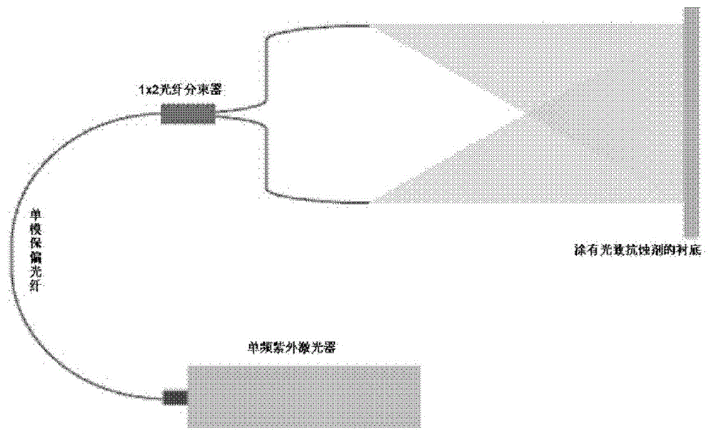
[0034] figure 1 The principle diagram of the all-fiber interference lithography system proposed by the present invention is schematically illustrated. The laser beam output from a 405nm single-frequency UV laser is coupled into a single-mode polarization-maintaining fiber (PMF). The PMF is connected to a 1x2 fiber optic beam splitter to obtain two laser beams with approximately equal intensities. The end face of the output fiber connected to the fiber splitter is directed towards the photoresist-coated substrate. Since a single-mode fiber with a small core diameter essentially behaves as a spatial fiber, it is preferable to obtain a circular Gaussian beam when emit...


PUM


Abstract

The present invention provides full-optical fiber laser interference lithography equipment and a method thereof. The full-optical fiber laser interference lithography equipment comprises: input coupling optical fiber for coupling a coherent laser beam from a laser source to an optical fiber beam splitter; the optical fiber beam splitter for splitting the coherent laser beam from the input coupling optical fiber into at least two sub-laser beams, and outputting the sub-laser beams through two or a plurality of output coupling optical fibers; and an adjusting unit for fixing the output coupling optical fibers and adjusting the positions and the angles of the output coupling optical fibers so as to adjust the sub-laser beams irradiating onto a substrate.

Description

technical field [0001] The present invention relates to the field of lithography. More specifically, the present invention relates to all-fiber laser interference lithography apparatus and methods using fiber beam splitters. Background technique [0002] Current laser interference lithography systems use glass beam splitters to split the original correlated laser beams in free space. Both the original laser beam and the split laser beam usually propagate in free space. Such optical arrangements require precise alignment which is very time consuming. Changing the interference pattern, especially changing the period, requires realignment of the entire optics. In addition, laser light propagating in free space is susceptible to environmental perturbations such as air currents or air fluctuations. [0003] Interference lithography is a technique for patterning submicron structures in arrays covering large areas. The interference of two or more beams of coherent light waves ...

Claims


Application Information

Patent Timeline
Patent Type & Authority Applications(China)
IPC IPC(8): G03F7/20G02B27/28
CPCG03F7/70408G02B6/3616G02B6/2856
Inventor 李文迪
Owner 李文迪
Learn More