Electric discharging device of rotation electrode

A technology of rotating electrodes and discharge devices, applied in the field of ions, can solve the problems of increasing airflow velocity and energy consumption, short life of cathodes with thin or thin structures, and high ozone yield

Inactive Publication Date: 2016-04-13
孙红梅
View PDF9 Cites 21 Cited by
  • Summary
  • Abstract
  • Description
  • Claims
  • Application Information

AI Technical Summary

Problems solved by technology

[0011] The object of the present invention is not to increase the airflow velocity and energy consumption, nor to use high-cost ultra-high-frequency high-voltage pulse power supply, to solve the short service life of the sharp or thin structure cathode in the above-mentioned plasma air purification method. Inhomogeneity and the problem of excessive ozone yield near the cathode, it is necessary to obtain uniform large-area plasma, suppress the ozone yield, and reduce the rapid ablation of the cathode

Method used


Image

  • Electric discharging device of rotation electrode
  • Electric discharging device of rotation electrode
  • Electric discharging device of rotation electrode

Examples


specific Embodiment approach 2

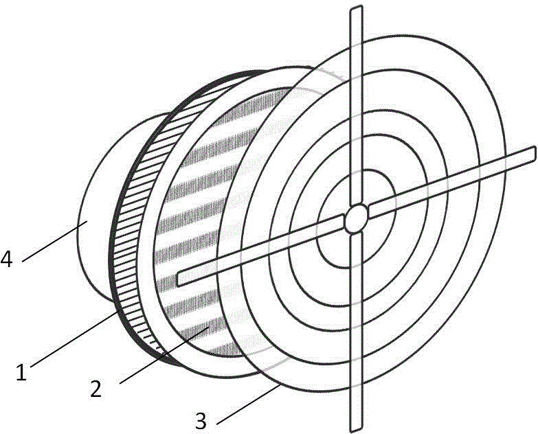
[0030] The discharge device of the centrifugal fan driving the rotating electrode of the specific embodiment 2 of the present invention, its structural diagram is as follows figure 2 shown.

[0031] The rotating electrode 2 is a circular plane structure with 9 strip-shaped wire mesh electrodes arranged in parallel on the metal ring. The circular rotating electrode 2 has the same diameter as the impeller 1 and is fixed on the impeller 1 through the metal ring; The strip wire mesh electrode interval is 10mm, the fixed electrode 3 is a fan metal protective net with a fence structure, the diameter is larger than the impeller diameter; the distance between the rotating electrode 2 and the fixed electrode 3 is 20mm, the driving voltage is 8kV, and the rated power of corona discharge is 10W ;The rated power of motor 4 is 90W, with three gears of high speed, medium speed and low speed, the speed is between 1200-2400r / m, the air supply distance of high speed gear is more than 10 meter...

specific Embodiment approach 3

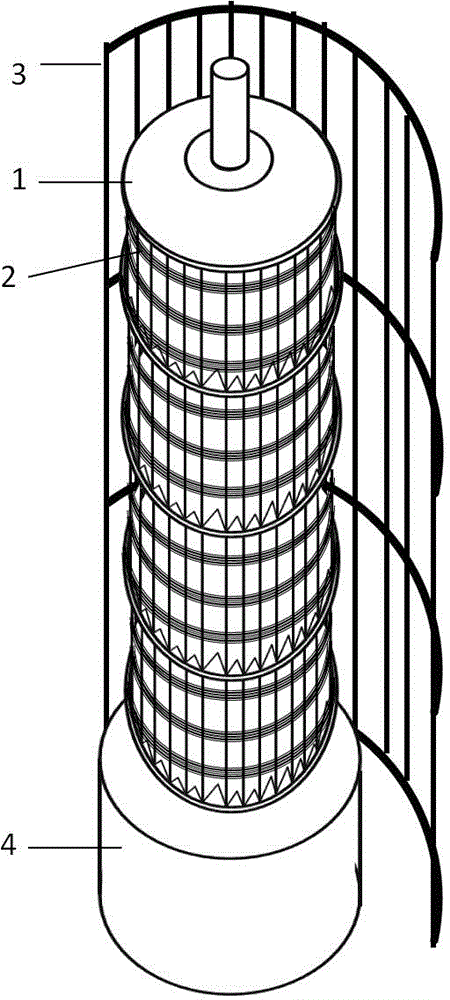
[0032] The specific embodiment 3 of the present invention is to apply the discharge device of the cross-flow fan to drive the rotating electrode in the tower fan. The partial structure diagram of the discharge device is as follows image 3 As shown, the overall schematic diagram of the tower fan is shown in Figure 5 shown.

[0033] The rotating electrode 2 is a wire mesh belt spirally wound on the wind wheel 1 of the cross-flow fan. The distance between the adjacent spiral rings of the metal belt is 10mm. The rotating electrode 2 is in electrical contact with the bearing of the wind wheel 1. The spiral Both ends of the rotating electrode 2 are fixed on the wind wheel 1; the rated power of the motor 4 is 180W, and there are three gears of high speed, medium speed and low speed. More than one meter, air volume 3000m 3 / h, the low speed gear is also more than 10 meters, and the air volume is 1800m 3 / h; the fixed electrode 3 is a two-fifths cylindrical surface dust collection...


PUM


Abstract

The invention belongs to the technical field of low-temperature plasma application, and relates to an electric discharging device of a rotation electrode. The device comprises an impeller, a rotation electrode, a fixed electrode, and an electric motor, wherein the rotation electrode is arranged between the electric motor and the fixed electrode, and is fixedly arranged on the impeller or a shaft of the electric motor. The electric motor drives the impeller and the rotation electrode to move. High voltage is applied between the rotation electrode and the fixed electrode, and corona discharging is generated between the two electrodes. Since the electric motor drives the rotation electrode to move, corona rotates with the movement to draw a large-volume plasma area. Plasma is uniformly dispersed in a whole airflow channel between the two electrodes. Therefore, the electric discharging device can be applied to an air purifier and allows no dead corner to be left during purification. Moreover, the rotation electrode can greatly reduce the ozone yield, and prolongs the service life of asymmetric electrodes.

Description

technical field [0001] The invention relates to the field of low-temperature plasma technology, in particular to a discharge device for a rotating electrode. Background technique [0002] In recent years, the problem of environmental degradation has become increasingly prominent, and the application of low-temperature plasma technology in environmental protection has also attracted more and more attention. Plasma organic waste gas purification, plasma wastewater purification, plasma automobile exhaust purification and plasma formaldehyde removal, TVOC and PM2.5 and other related technologies and product development have received unprecedented attention. [0003] PM2.5 from fossil fuel combustion and formaldehyde and TVOC pollution from interior decoration have increasingly become important factors that seriously affect people's quality of life. Taking home decoration pollution as an example, the existence of volatile organic gases headed by formaldehyde in the indoor air se...

Claims


Application Information

Patent Timeline
Patent Type & Authority Applications(China)
IPC IPC(8): B03C3/41H05H1/24
Inventor 孙红梅
Owner 孙红梅
Why Eureka
Try Eureka