Supercharge Your Innovation With Domain-Expert AI Agents!

Nozzle component, vapor deposition device and method for manufacturing organic light emitting diode device

A technology of nozzles and components, which is applied in the field of organic light-emitting diode displays, can solve the problems of difficult accurate control and low temperature, and achieve the effects of not easy to lose, improve performance, and improve equipment utilization rate

Active Publication Date: 2018-03-30
BOE TECH GRP CO LTD +1
View PDF5 Cites 0 Cited by
  • Summary
  • Abstract
  • Description
  • Claims
  • Application Information

AI Technical Summary

Problems solved by technology

[0004] The nozzle parts of the current linear heating source are all independently made of titanium metal, the height is relatively large, and such as figure 1 As shown, the heating wire 4 that maintains the temperature of the nozzle 2 is generally designed at the corner formed by the body 1 and the bearing base 5 due to the need for fixing, so that the heat of the heating wire 4 is mainly in the lower part of the nozzle, and the heat in the upper part of the nozzle 2 passes through the titanium metal Conduction and heat radiation are obtained, resulting in a lower temperature on the upper part of the nozzle 2, especially the top, and it is difficult to accurately control

Method used


Image

  • Nozzle component, vapor deposition device and method for manufacturing organic light emitting diode device
  • Nozzle component, vapor deposition device and method for manufacturing organic light emitting diode device
  • Nozzle component, vapor deposition device and method for manufacturing organic light emitting diode device

Examples


Embodiment Construction

[0024] The specific embodiments of the present invention will be further described below in conjunction with the accompanying drawings. The following examples are only used to illustrate the technical solution of the present invention more clearly, but not to limit the protection scope of the present invention.

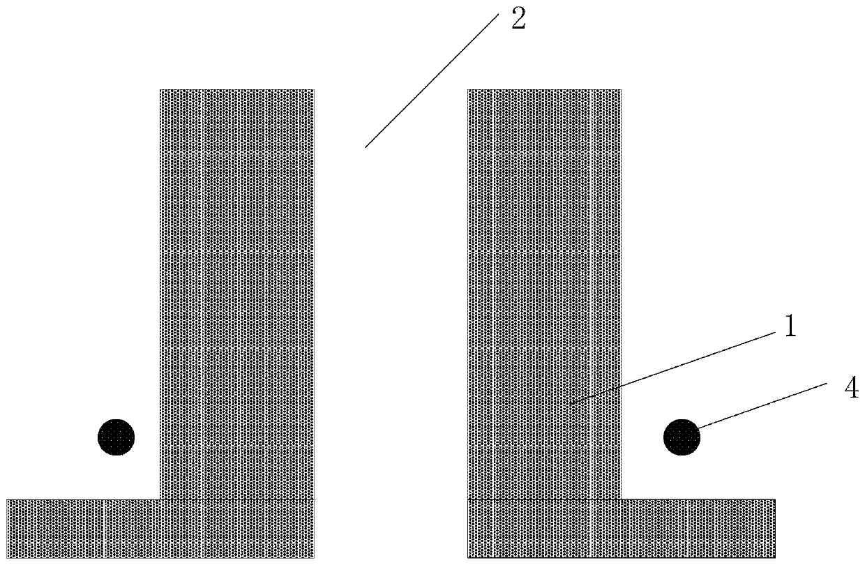
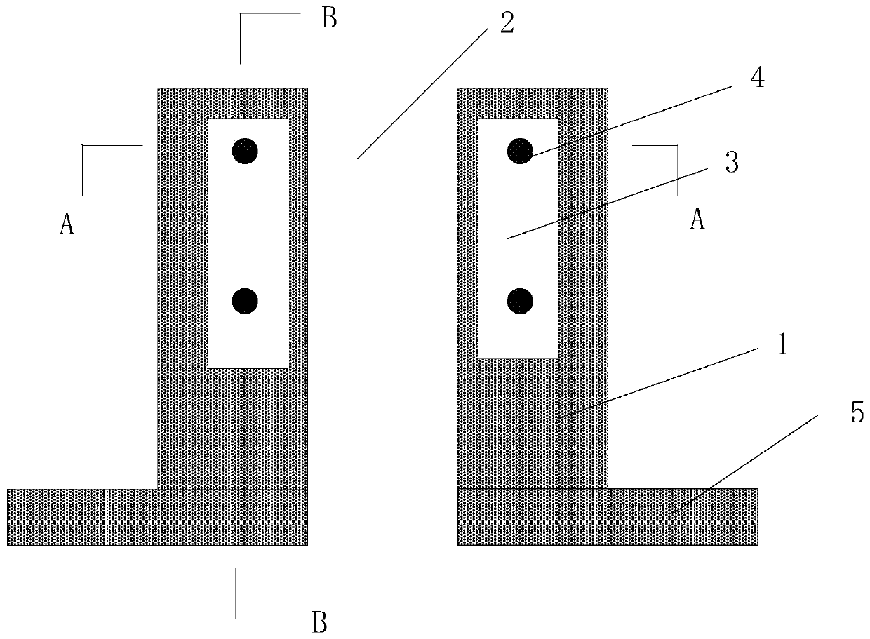
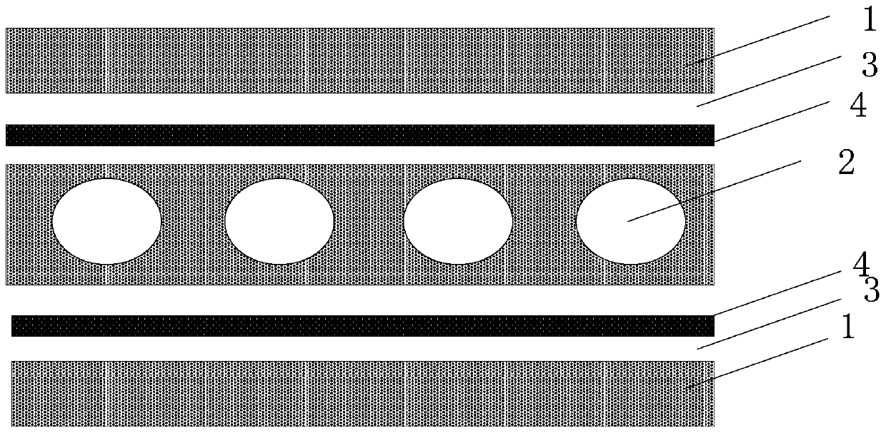
[0025] In a first embodiment of the present invention there is provided a nozzle assembly such as figure 2 , 3 , 4, including a body 1 provided with a nozzle 2, the body 1 is also provided with a hollow cavity 3 spaced apart from the nozzle 2, and a heating element 4 is disposed in the hollow cavity 3. In the present invention, the nozzle 2 is a hollow passage for ejecting evaporation materials surrounded by the materials constituting the body 1, and includes two openings, one of which is generally used to communicate with the evaporation chamber of the evaporation equipment.

[0026] Through the above scheme, since the heating element 4 is provided in the hollow c...


PUM


Abstract

The invention relates to the technical field of organic light emitting diode display, and provides a nozzle component, an evaporation device and a method for manufacturing an organic light emitting diode device. In the present invention, a heating element is provided in the hollow cavity spaced apart from the nozzle. When the organic material is evaporated, the heating element can be heated to raise the temperature, so that the temperature of the surrounding wall of the nozzle rises to be basically consistent with that in the evaporation chamber or slightly higher than that in the evaporation chamber. The temperature in the coating chamber and thus the nozzle is kept within an appropriate range, neither too low to condense the organic material in the nozzle nor too high to carbonize the organic material. At the same time, since the organic material does not condense in the nozzle, there is no need to shut down the vapor deposition device to clean the nozzle, which improves the utilization rate of the equipment. Since the organic material is no longer condensed at the nozzle or carbonized at a high temperature, the thickness of the organic material layer formed by evaporation meets the design requirements, and the material will not deteriorate, which improves the performance of the organic light emitting diode device.

Description

technical field [0001] The invention relates to the field of organic light emitting diode display technology, in particular to a nozzle component, an evaporation device and a method for manufacturing an organic light emitting diode device. Background technique [0002] At present, the mainstream preparation process of organic light-emitting diodes (OLEDs) is evaporation technology. Evaporation technology mainly uses the principle of thermal evaporation of organic materials, that is, filling organic materials into a heating source and heating them in a vacuum environment to make solids The organic material is melted and volatilized or sublimated to form a gaseous state, and the gas flow of the organic material is deposited on the glass substrate to form layers of organic thin films to prepare OLED devices. [0003] The gas flow of the organic material comes out of the crucible through the nozzle of the heating source. However, due to the instability of the process or the soli...

Claims


Application Information

Patent Timeline
Patent Type & Authority Patents(China)
IPC IPC(8): C23C14/26C23C14/12C23C14/54H01L51/56H10K99/00
CPCC23C14/12C23C14/26C23C14/54H10K71/164C23C14/243H10K71/00B05B1/20B05B9/002
Inventor 邹清华
Owner BOE TECH GRP CO LTD
Features
  • R&D
  • Intellectual Property
  • Life Sciences
  • Materials
  • Tech Scout
  • Unparalleled Data Quality
  • Higher Quality Content
  • 60% Fewer Hallucinations
Learn More