
Waste gas heat recovery and purification device for setter

A technology of purification device and shaping machine, which is applied to heating devices, indirect heat exchangers, heat exchanger types, etc., can solve the problems of short input and output gas passages, short heat exchange length, etc., to achieve simple structure and reduce manual intervention. , the effect of stable work

Active Publication Date: 2016-04-13
广东联和环保科技有限公司
View PDF5 Cites 4 Cited by
  • Summary
  • Abstract
  • Description
  • Claims
  • Application Information

AI Technical Summary

Problems solved by technology

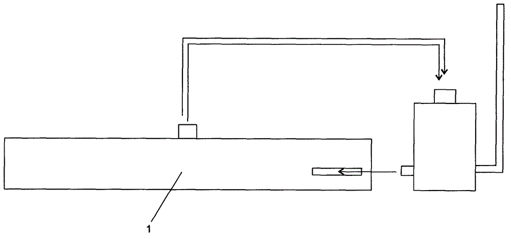
[0010] In order to solve the defects of the above old equipment, the present invention solves the old defects along the following technical ideas. One is to have the shortest possible input and output gas passages, and avoid the exposure of high temperature parts in the overall structure to reduce the mechanical Body heat radiation avoids heat loss, and at the same time builds airflow circulation inside the sizing machine to avoid heat energy from overflowing from the sizing machine gap to reduce heat loss; second, there must be sufficient channel caliber, heat exchange length as short as possible, and avoid the corner structure of the pipe , to reduce clogging and achieve large-displacement heat exchange, while avoiding the use of heat medium exchange technology and special-shaped heat exchange tube structure to simplify the complexity of the overall structure, reduce production costs and maintenance costs; the third is the connection between the input and output gas channels The interface of the sizing machine should be adjustable to facilitate the flexible deployment of the product of the present invention, especially to facilitate the transformation of the old sizing machine

Method used


Image

  • Waste gas heat recovery and purification device for setter
  • Waste gas heat recovery and purification device for setter
  • Waste gas heat recovery and purification device for setter

Examples


Embodiment Construction

[0050] figure 1 It is a commonly used external tower-type heat recovery device. It uses the inherent top hot exhaust gas discharge port of the main body of the setting machine 1, and uses pipelines to transport it to the tower-type heat recovery device for treatment, and the heated clean gas also passes through the pipeline. No matter what the heat recovery efficiency of the tower heat recovery device is, the long-distance exhaust gas transmission pipeline will inevitably lead to a large loss of heat energy. And due to the limited space of the tower heat recovery device, in order to improve the heat exchange capacity, it is often necessary to use finned tubes or corrugated tubes as heat exchange components in order to increase the heat exchange area, and to use hot oil exchange technology or water vapor heat exchange technology to improve Heat exchange efficiency, the internal heat exchange structure is more complicated, the failure rate is high, the cost is increased, and the...


PUM


Abstract

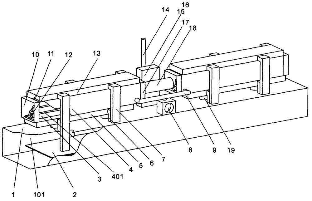
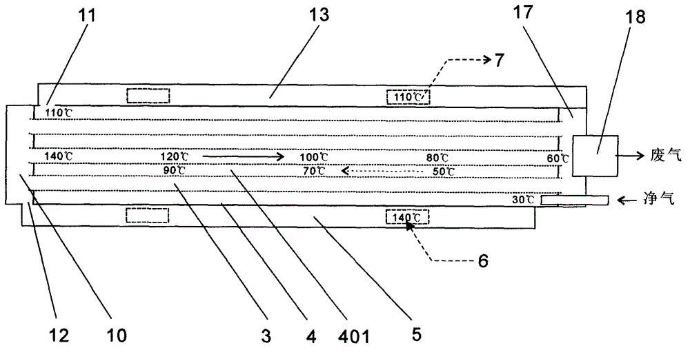
The invention discloses a waste gas heat recovery and purification device for a setter. The device comprises heat exchange cases arranged above the setter and heat exchange tube stacks in the heat exchange cases, wherein waste gas chambers are arranged at the front and rear ends of the heat exchange tube stacks; clean gas collection passages are arranged above the heat exchange cases; the front ends of the clean gas collection passages are communicated with heat exchange chambers in the heat exchange cases; clean gas inlet pipes are arranged on the lateral surfaces of the clean gas collection passages, and penetrate through the top of the setter to be inserted into the upper parts of heaters; waste gas collection passages are arranged below the heat exchange cases; the front ends of the waste gas collection passages are communicated with the front-end waste gas chambers; the lateral surfaces of the waste gas collection passages are communicated with openings in the top of the setter through waste gas collection pipes; the hot waste gas of the rear-end waste gas chambers is exhausted into gas flow boiling dust removal purification cases for treatment through waste gas exhaust motors, and then is discharged into the air; blower motors are arranged at the tail ends of the heat exchange cases to introduce fresh air. The device is simple in structure, large in heat exchange area, high in heat exchange efficiency, difficult to block and low in failure rate, the tubes have large diameters, fewer bends and small lengths, hot gas can be internally circulated, and waste gas emission is avoided by such an ideal structure, so that remarkable energy saving and emission reduction effects, low cost and high benefits are achieved.

Description

technical field [0001] The invention relates to a heat recovery and purification device for processing a large amount of hot waste gas, especially a heat recovery and purification device for the waste gas of a setting machine. Background technique [0002] my country is the world's largest producer and exporter of textiles and clothing, and the sustainable development of the textile industry is crucial to my country's economic development and solving social employment problems. The textile industry is also a high-pollution and high-energy-consumption industry. The energy consumption of the setting machine is particularly serious. Generally, the internal heating temperature of the setting machine is 160-220 degrees Celsius, and the exhaust gas discharge temperature is between 150-210 degrees Celsius. 2500-6000 cubic meters per hour, a single setting machine consumes 400,000-1.2 million kcal of energy. It is estimated that the heat energy consumed by fabric processing and sett...

Claims


Application Information

Patent Timeline
Patent Type & Authority Applications(China)
IPC IPC(8): D06C7/02B01D47/02F28D1/053F24J3/00
CPCY02P70/10
Inventor 苟亚松
Owner 广东联和环保科技有限公司
Learn More