A heating furnace with modular lining

A heating furnace and lining technology, applied in the field of heating furnaces, can solve the problems of no construction work space, loose insulation lining, difficulty in repairing damage, etc., and achieve the effects of reducing maintenance work, changing structural functions, and shortening construction period

Active Publication Date: 2018-06-26
THE CHALLENGE PETROCHEM MACHINERY CORP
View PDF5 Cites 0 Cited by
  • Summary
  • Abstract
  • Description
  • Claims
  • Application Information

AI Technical Summary

Problems solved by technology

After the innovation of modular construction technology of heating furnace solved the coordination problem of modern engineering construction, new problems were exposed in the construction of heating furnace, that is, the strength of non-metallic insulation lining is lower than that of steel structure, and the modules are loose structures with large gaps Between the furnace walls, between the furnace wall and the top or bottom, at the entrances and exits, and at the corners of the flow channels are the stress nodes of the structure. Long-distance transportation and hoisting of large modules are likely to cause deformation of the modules and damage to the insulation lining. Loosening, cracking and other damage
On the other hand, the structural stress nodes of the module are also the structural stress nodes of the heating furnace. When the flue gas passes through this special structure, it is often subjected to changing obstructions and pressures, resulting in flow state changes such as vortices and impacts, which further damage the lining. , resulting in air leakage from the furnace wall during the operation of the heating furnace, which reduces thermal efficiency and is not conducive to energy saving and emission reduction
Moreover, because the furnace module is full of coils and there is no room for construction work, the repair of these damages is very difficult

Method used


Image

  • A heating furnace with modular lining
  • A heating furnace with modular lining
  • A heating furnace with modular lining

Examples


Embodiment 1

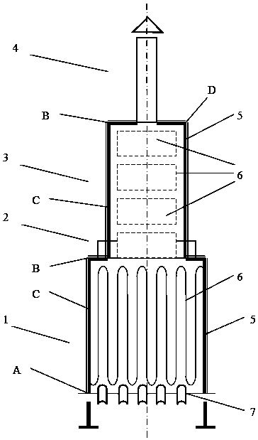
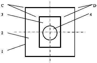
[0055] One of the specific implementations of a heating furnace with a module lining of the present application, refer to the prior art figure 1 and figure 2 As shown, including the functional structure of the heating furnace in the prior art, the structure includes a radiation section 1 at the bottom, a transition section 2 at the top of the radiation section 1, a convection section 3 at the top of the transition section 2, and a Chimney 4, the main structure of the heating furnace includes furnace wall 5, elbow box, coil pipe 6 and burner 7, and furnace wall 5 is formed by laying and welding thin steel plates on profiled steel frames. The innovations of this application are as follows: figure 1 , figure 2 , image 3 and Figure 4 As shown, a set of welding claw nails is arranged on the inner side of the furnace wall 5, and the heat insulation lining layer is poured between the welding resistance claw nails or a preformed heat insulation module lining is installed. The h...

Embodiment 2

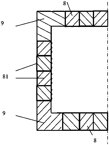
[0059] The second specific embodiment of a heating furnace with a modular lining of the present application, the main technical solution of this embodiment is the same as that of embodiment 1, and the features not explained in this embodiment adopt the explanation in embodiment 1, in This will not be repeated here. The difference between this embodiment and Embodiment 1 is that the three-dimensional heat insulation module lining unit 10 is a three-dimensional heat insulation module lining unit 10 formed by the intersection of three planes. refer to Figure 4 As shown, the three planes are the top surface 2xoz, the right side 2yoz, and the front and back 2xoy that constitute the cavity, and the module lining has three L-shaped end surfaces, namely, the bottom end surface 1xz, the right end surface 1yz, and the front surface 1xy. When building the furnace wall 5, the three end faces are respectively spliced ​​with other modules. Three planes form a closed cavity, which has a c...

Embodiment 3

[0062] The third specific implementation mode of changing a heating furnace with a modular lining of the present application, the main technical solution of this embodiment is the same as that of embodiment 2, and the features not explained in this embodiment adopt the explanation in embodiment 2, No further details will be given here. The difference between this embodiment and Embodiment 1 is that the three planes are quadrilateral planes. This structure is relatively easy to process, and the assembly is relatively convenient and simple.

[0063] Specifically, the three-dimensional thermal insulation module lining unit 10 is a shaped cavity module lining formed by the intersection of three rectangular planes. This kind of brick-shaped module refers to Figure 4 shown. A square is a special form of a rectangle, and all or part of the three rectangular planes may be square planes. Figure 5 The 21xoz surface shown is Figure 4 A top view of 2xoz on the middle top.

[0064]...


PUM


Abstract

The invention discloses a heating furnace with a module liner. The heating furnace comprises a furnace body; the furnace body includes a furnace top plate, furnace walls and a furnace baseplate; a thermal insulation module liner is arranged on the inner side of the furnace body, and is assembled through assembly welding jaw nails; and the thermal insulation module liner includes one-dimensional thermal insulation module liner units mounted on the furnace top plate or the furnace walls or the furnace baseplate, two-dimensional thermal insulation module liner units mounted in the corner of two furnace walls or the corners of the furnace walls and the furnace top plate or the corners of the furnace walls and the furnace baseplate, and three-dimensional thermal insulation module liner units mounted in the intersections of two furnace walls and the furnace baseplate or the intersections of two furnace walls and the furnace top plate. The heating furnace uses the module liner for thoroughly solving the problem of module damage in structure joints caused in long-distance transportation and lifting process of large modules, improves the structure stability, reduces splicing gaps, prevents air leakage of the furnace walls, improves the construction efficiency, and shortens the project duration.

Description

technical field [0001] The application relates to the technical field of heating furnaces in petroleum refining, petrochemical and other chemical fields, and in particular to a heating furnace with a modular lining. Background technique [0002] Heating furnace is the leader in petrochemical industry, including atmospheric furnace, vacuum furnace, hydrogen production furnace, reforming furnace, coking furnace, reforming furnace and cracking furnace. The four sides of the main body of the heating furnace are surrounded by tall furnace walls. The furnace wall is covered with welded steel plates on steel frames such as I-beams. The steel plates are distributed with welded insulation nails, and heat insulation and wear-resistant materials or materials are cast between the insulation nails. Insulated module lining. In the case of tube furnaces, so-called tube furnaces, the function of which is to heat the medium (oil or gas) to the temperature required for the process, the brack...

Claims


Application Information

Patent Timeline
Patent Type & Authority Patents(China)
IPC IPC(8): F27D1/10F27D1/04
CPCF27D1/04F27D1/10Y02P20/10
Inventor 陈孙艺
Owner THE CHALLENGE PETROCHEM MACHINERY CORP
Why Eureka
Try Eureka