Magnetic metal detection sensor

A magnetic metal and magnetoelectric sensor technology, applied in the direction of electric/magnetic exploration, instruments, measuring devices, etc., can solve the problems of high power consumption, many ancillary equipment, inconvenient operation, etc., and achieve reduced size and weight, lightweight Hand-held operation, the effect of convenient hand-held operation

Inactive Publication Date: 2016-04-13
PEKING UNIV
View PDF4 Cites 20 Cited by
  • Summary
  • Abstract
  • Description
  • Claims
  • Application Information

AI Technical Summary

Problems solved by technology

Among them, the induction coil has high precision, but it can only obtain the rate of change of the magnetic field signal, which is not suitable for low-frequency measurement, and its large size is not conducive to miniaturization; the fluxgate sensor is small in size, but has high power consumption and poor impact resistance. The detection distance is relatively short; the cost of the Hall device is low, it can be used for low-frequency measurement, and the operating temperature range is wide, but the detection sensitivity is not high; the sensitivity of the optical pump and nuclear precession magnetometer is high, but it requires harsh working conditions and ancillary equipment These disadvantages limit its wide application; the magnetoresistive sensor has the advantages of low power consumption and small size, but its detection distance needs to be further improved
[0004] In summary, the use of existing metal detectors for detection has the disadvantages of being inconvenient to carry, inconvenient to operate, and difficult to complete the detection task, or there are problems of high operating frequency and high equipment cost
For the detection of magnetic metals, the existing technology cannot provide a magnetic metal detector that can be used in low frequency, high sensitivity, long detection distance, low power consumption, low cost and light weight

Method used


Image

  • Magnetic metal detection sensor
  • Magnetic metal detection sensor
  • Magnetic metal detection sensor

Examples


Embodiment Construction

[0031] Below in conjunction with accompanying drawing, further describe the present invention through embodiment, but do not limit the scope of the present invention in any way.

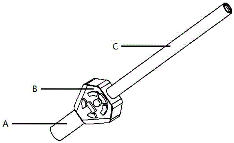
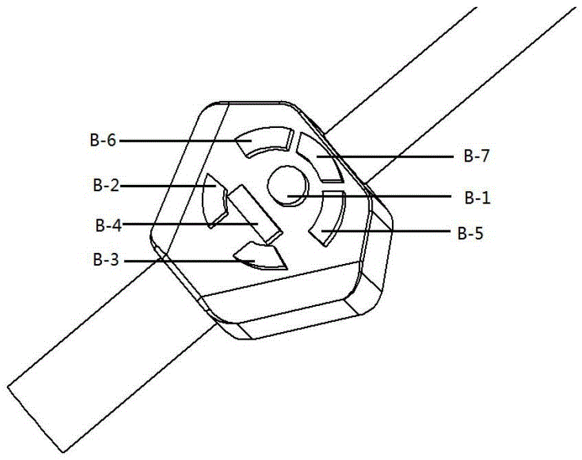
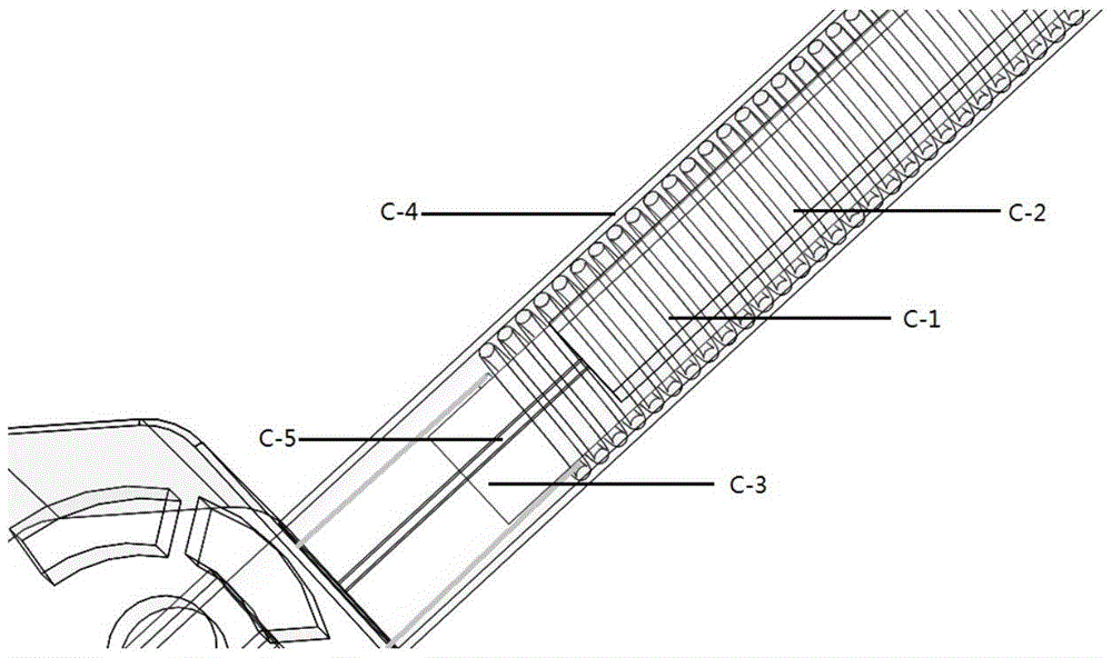
[0032]The invention provides a metal detection sensor, especially a magnetic metal detection sensor, which includes a high-sensitivity magnetoelectric sensor and a signal generating device; the signal generating device is composed of a signal generating circuit and an excitation coil; the magnetoelectric sensor is made of a magnetostrictive material Composed of piezoelectric materials, the magnetoelectric sensor has high magnetic detection sensitivity due to the piezoelectric effect of the magnetostrictive material and the piezoelectric effect of the piezoelectric material and its strong magnetoelectric coupling effect in the resonant vibration state; The excitation coil is wound around the magnetoelectric sensor, and the magnetoelectric sensor outputs a corresponding magnetoelectric coupling voltage ...


PUM


Abstract

The invention discloses a magnetic metal detection sensor, comprising an electromagnetic sensor and a signal generator; the magneto-electric sensor is made of a magnetostrictive material and a piezoelectric material; piezomagnetism of the magnetostrictive material, the piezoelectric effect of the piezoelectric material and the strong magnetoelectric coupling effect under resonant vibration enables the magnetoelectric sensor to have high magnetic detection sensitivity; the signal generation device consists of a signal generation circuit and an excitation coil which is wound around the external of the magneto-electric sensor; and an alternative and bias magnetic field which is provided by the signal generation device enables the magneto-electric sensor to output corresponding magneto-electric coupling voltage signals; and the detected signal can be outputted and displayed through multiple modes. The invention is simple in manufacture technology, compact and light in structure, and easy to carry and hand-held operation, can be effectively applicable to the magnetic metal detection field and has a high application value on the metal detection imaging.

Description

technical field [0001] The invention relates to metal detection equipment, in particular to a novel magnetic metal detection sensor. Background technique [0002] Metal detectors are widely used in industrial production, food testing, safety inspection, etc. It can detect metal objects in the ground, industrial products and human body, and is an important detection equipment. At present, the mainstream metal detectors use the principle of electromagnetic induction - using the excitation coil to generate an alternating magnetic field. When a metal object approaches, an eddy current magnetic field will be generated, which will be sensed by the detection coil. In order to improve the detection ability, there are generally two methods: one is to increase the area of ​​the excitation and detection coils, but this limits the development of metal detectors in the direction of compact structure, light weight, and flexible detection, especially for some metal detectors. Special spat...

Claims


Application Information

Patent Timeline
Patent Type & Authority Applications(China)
IPC IPC(8): G01V3/08
CPCG01V3/08
Inventor 董蜀湘石花朵储昭强王蕾
Owner PEKING UNIV
Why Eureka
Try Eureka