Automatic tank bottom blowdown system

A sewage discharge system and automatic sewage discharge technology, applied in the direction of sustainable manufacturing/processing, sustainable packaging, containers, etc., can solve the problems of wasting manpower, material and financial resources, manual cleaning hidden dangers, inaccurate crude oil measurement, etc., to reduce downtime Save time, save manpower, material and financial resources, and ensure safety and reliability

Active Publication Date: 2016-04-20
惠金波
View PDF13 Cites 3 Cited by
  • Summary
  • Abstract
  • Description
  • Claims
  • Application Information

AI Technical Summary

Problems solved by technology

[0002] Oil tanks and water tanks are commonly used containers in oil fields. Since crude oil and sewage contain a large amount of sediment, most of the sediment will settle at the bottom of the tank after a period of use. If they are not cleaned in time, the measurement of crude oil will be inaccurate. More seriously, it will lead to premature wear of pumps and valves and blockage of pipelines, which will bring huge economic losses to oil field production; at present, the common cleaning method is to empty the oil or water in the tank, open the manhole, and use manual Cleaning; this cleaning method not only seriously affects production, but also wastes a lot of manpower, material resources and financial resources each time, and because the crude oil contains harmful gases, there is a certain safety risk in the cleaning process, especially in summer when the high temperature, the adhesion on the pipe wall The light oil and gas in the crude oil will decompose into harmful gas at high temperature, and when the concentration reaches a certain level, it will explode with an open flame, endangering personal safety, and there is a great potential safety hazard in manual cleaning

Method used


Image

  • Automatic tank bottom blowdown system
  • Automatic tank bottom blowdown system
  • Automatic tank bottom blowdown system

Examples


Embodiment 1

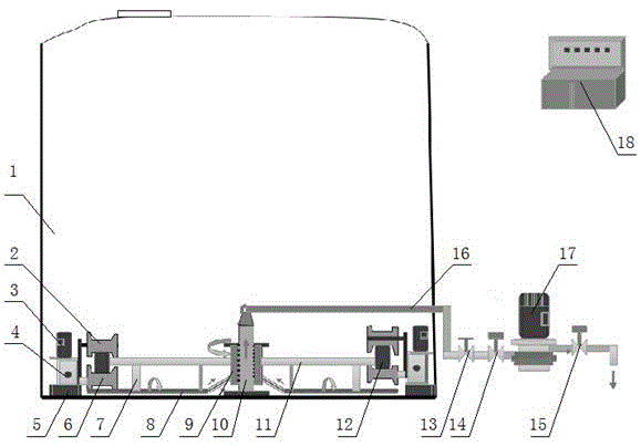
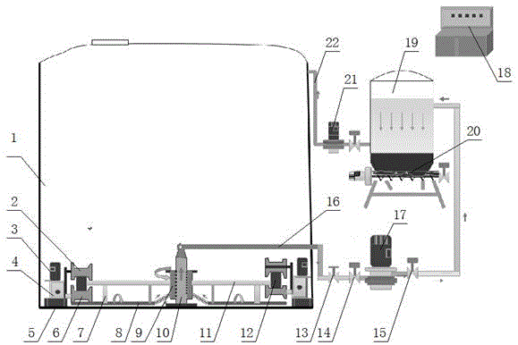
[0029] see figure 1 : automatic sewage discharge system at the bottom of the tank of the present invention, comprising the sewage suction device in the tank that is arranged in the oil storage or water storage tank body 1 and the sewage discharge device outside the tank that is arranged on the tank body 1, the sewage suction device in the tank and the sewage discharge device outside the tank The device is communicated through the sewage pipe 16. The sewage suction device in the tank includes a driving mechanism and a turntable 12 driven by the driving mechanism. The diameter of 1 is adjusted, and the tank body 1 with a diameter of less than 5 meters can use 3 sets of driving mechanisms. Each set of driving mechanisms includes an underwater motor 3 and a roller driven by the underwater motor 3 and connected to the turntable 12. Assemblies, the underwater motor 3 is connected to the roller assembly through the underwater worm gear reducer 4, and the speed is effectively reduced ...

Embodiment 2

[0034] see figure 1 : Preferably, the difference between this embodiment and Embodiment 1 is that the underwater worm gear reducer 4 and the hollow column 10 of the sewage suction device in the tank are respectively adsorbed on the bottom of the tank body 1 by a permanent magnetic sucker 5, installed Simple, easy to maintain and suitable for thin-walled tanks. The sewage suction pipe 8 is matched with the bottom inner wall of the tank body 1, and the arc bottom line or inclination of the sewage suction and spray pipe is set according to the structure of the tank bottom. If the bottom of the tank body 1 is a curved surface structure, the sewage suction pipe 8 has a matching curvature. 8 has an effective fit with the bottom of the tank body 1, so that no dead space is left for dirt cleaning.

Embodiment 3

[0036] see figure 1: Further preferably, the difference between this embodiment and embodiment two is that the tank bottom automatic sewage discharge system of the present invention also includes an automatic control device 18 electrically connected with the sewage suction device in the tank and the sewage discharge device outside the tank, automatically The control device 18 is a control cabinet with an automatic operation mode and a manual operation mode. The gate valve includes a first electric gate valve 14 arranged on the inlet side of the sewage suction pump 17, a second electric gate valve 15 on the outlet side, and a manual gate valve 13 arranged between the first electric gate valve 14 and the tank body 1, through an automatic control device The control program of 18 can effectively realize the regular automatic operation of the system according to the set program. The driving mechanism adopts a hydraulic reducer to drive the roller assembly, which can be effectively...


PUM


Abstract

The invention discloses an automatic tank bottom blowdown system. The system comprises a tank inside dirt suction device and a tank outside blowdown device which are connected with each other through a blowdown pipe, wherein the tank inside dirt suction device drives a turntable by a drive mechanism, a plurality of dirt suction pipes are distributed on the turntable, and the turntable and the dirt suction pipes rotate with a hollow stand column as a center of circle. By virtue of strong negative-pressure attraction generated by a dirt suction pump of the tank outside blowdown device, dirt is sucked into the dirt suction pipes, then transported into a column sleeve type collection cavity to be gathered, and finally discharged from the tank outside blowdown device through the blowdown pipe, thereby automatically discharging dirt at the bottom of a tank, avoiding inconvenience of manual cleaning in a traditional way, shortening shutdown time, improving production efficiency, lowering production cost greatly, saving manpower and material resources as well as financial resources, and avoiding potential safety hazard caused by manual cleaning. The automatic tank bottom blowdown system is safe and reliable, is reasonable in structure, convenient to operate and high in automation degree, facilitates recycling and retreatment of dirt, and avoids environment pollution likely to be caused by manual cleaning.

Description

technical field [0001] The invention belongs to the technical field of blowdown at the bottom of large tanks, and in particular relates to an automatic blowdown system for tank bottoms which is suitable for cleaning and blowdown at the bottom of oil tanks or water tanks in oil fields. Background technique [0002] Oil tanks and water tanks are commonly used containers in oil fields. Since crude oil and sewage contain a large amount of sediment, most of the sediment will settle at the bottom of the tank after a period of use. If they are not cleaned in time, the measurement of crude oil will be inaccurate. More seriously, it will lead to premature wear of pumps and valves and blockage of pipelines, which will bring huge economic losses to oil field production; at present, the common cleaning method is to empty the oil or water in the tank, open the manhole, and use manual Cleaning; this cleaning method not only seriously affects production, but also wastes a lot of manpower, ...

Claims


Application Information

Patent Timeline
Patent Type & Authority Applications(China)
IPC IPC(8): B65D88/72
CPCB65D88/72Y02W30/80
Inventor 梅娟沈和平彭耕郭韬惠金波
Owner 惠金波
Why Eureka
Try Eureka