Jagged annular needleless static spinning device and application method thereof

An electrospinning, needle-free technology, applied in textiles and papermaking, filament/thread forming, fiber processing, etc., can solve the problems of non-oriented nanofiber product structure, non-automatic solution supply, and low nanofiber output. Achieve the effect of solving the uncontrollable structure of nanofibers, realizing industrialized preparation, and solving the problem of easy volatilization of solvents

Active Publication Date: 2016-04-20
DONGHUA UNIV
View PDF9 Cites 36 Cited by
  • Summary
  • Abstract
  • Description
  • Claims
  • Application Information

AI Technical Summary

Problems solved by technology

[0006] The technical problem to be solved by the present invention is to provide a zigzag annular needle-free electrospinning device and its use method, which solves the problem that the solution cannot be automatically supplied in the current electrospinning process, the solvent is easily volatile, the solution is not fully utilized, and the nanofiber Low yield and non-orientation of the final nanofiber product structure

Method used


Image

  • Jagged annular needleless static spinning device and application method thereof
  • Jagged annular needleless static spinning device and application method thereof

Examples


Embodiment 1

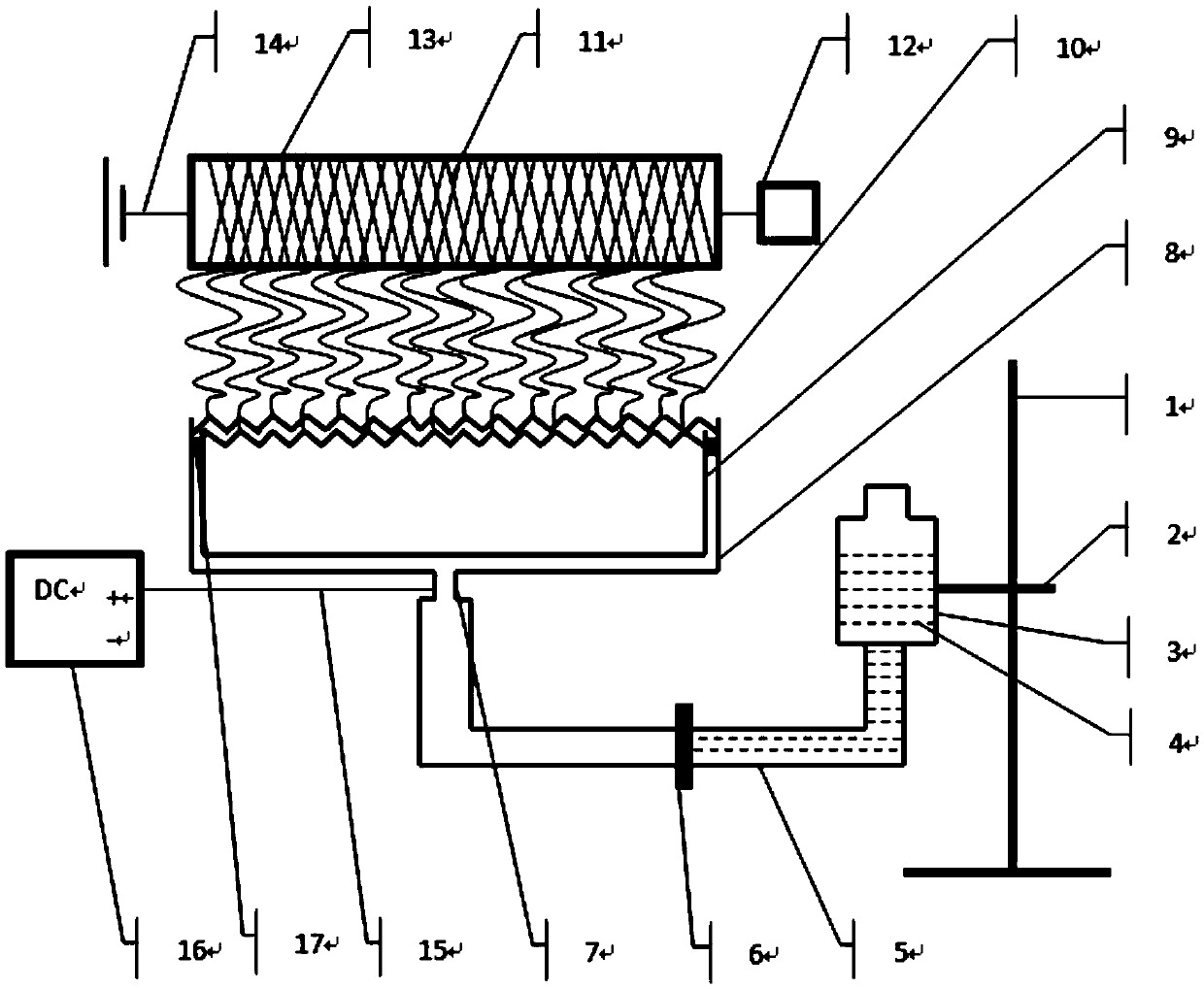
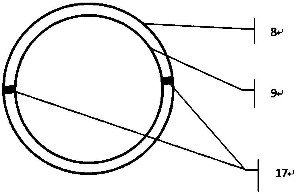
[0043] Next, nanofibers are prepared by using a polymer solution prepared from polyacrylonitrile (PAN) and dimethylformamide (DMF). The mass fraction of the prepared PAN polymer solution is 10%. Connect the liquid storage bottle 3 and the central copper metal tube 7 at the bottom of the outer ring liquid tank with the catheter 5, turn off the middle switch 6 of the catheter, and then fill the liquid storage bottle 3 with an appropriate amount of prepared PAN polymer solution 4 ; Turn on the middle switch 6 of the catheter, and the polymer solution 4 slowly flows into the annular slit formed by the zigzag outer ring liquid tank 8 and the inner ring liquid tank 9 through the catheter tube; height, so that the polymer solution overflows in the annular slit formed by the zigzag outer ring liquid tank 8 and the inner ring liquid tank 9, it is advisable to ensure that the liquid level overflows between the annular slits but does not flow out; The metal drum 13 is connected with the...

Embodiment 2

[0045] Connect the liquid storage bottle 3 and the central copper metal tube 7 at the bottom of the outer ring liquid tank with the catheter tube 5, close the middle switch 6 of the catheter tube, and then fill the liquid storage bottle 3 with an appropriate amount of PAN with a mass fraction of 10%. Polymer solution 4; open the middle switch 6 of the catheter, and the polymer solution 4 slowly flows into the annular slit formed by the zigzag outer ring liquid tank 8 and the inner ring liquid tank 9 through the catheter tube; adjust the storage through the clip 2 The height of the liquid bottle 3 makes the polymer solution overflow in the annular slit formed by the zigzag outer ring liquid tank 8 and the inner ring liquid tank 9, ensuring that the liquid level overflows between the annular slits but does not flow out It is advisable; connect the metal drum 13 with the ground wire 14, turn on the motor 12 connected to the metal drum 13, set the distance from the main shaft of th...

Embodiment 3

[0047] Connect the liquid storage bottle 3 and the central copper metal tube 7 at the bottom of the outer ring liquid tank with the catheter tube 5, close the middle switch 6 of the catheter tube, and then fill the liquid storage bottle 3 with an appropriate amount of PAN with a mass fraction of 10%. Polymer solution 4; open the middle switch 6 of the catheter, and the polymer solution 4 slowly flows into the annular slit formed by the zigzag outer ring liquid tank 8 and the inner ring liquid tank 9 through the catheter tube; adjust the storage through the clip 2 The height of the liquid bottle 3 makes the polymer solution overflow in the annular slit formed by the zigzag outer ring liquid tank 8 and the inner ring liquid tank 9, ensuring that the liquid level overflows between the annular slits but does not flow out It is advisable; connect the metal drum 13 with the ground wire 14, turn on the motor 12 connected to the metal drum 13, set the distance from the main shaft of th...


PUM

PropertyMeasurementUnit
diameteraaaaaaaaaa
lengthaaaaaaaaaa
lengthaaaaaaaaaa

Abstract

The invention relates to a jagged annular needleless static spinning device and an application method thereof. The device comprises a liquid supply system and a nanofiber collection system. The liquid supply system is in the structure of a communicating vessel composed of a liquid storage bottle and a jagged annular needleless sprayer. The jagged annular needleless sprayer is in the gap structure composed of an outer annular liquid groove and an inner annular liquid groove. The center of the bottom of the outer annular liquid groove is provided with a metal pipe. The center of the bottom of the liquid storage bottle is connected with one end of a liquid guide pipe, the other end of which is connected with the metal pipe. The liquid guide pipe is provided with a switch. By turning off the switch on the liquid guide pipe, a proper amount of polymer solutions is added into the liquid storage bottle. By turning on the switch, polymer solutions flow into the annular gap formed by the jagged outer annular liquid groove and the inner annular liquid groove. By adjusting the height of the liquid storage bottle, polymer solutions can overflow the annular gap. By turning on a motor, a metal cylinder is guaranteed to normally rotate at the certain speed. By turing on a high-voltage power supply, voltage is slowly increased. The jagged annular needleless static spinning device and the application method thereof help to achieve automatic supply of solutions to the sprayer and operation is performed conveniently.

Description

technical field [0001] The invention belongs to the technical field of nano electrospinning and textile machinery, and in particular relates to a zigzag annular needle-free electrospinning device and a use method thereof. Background technique [0002] Electrospinning technology is one of the effective methods for preparing nanofiber materials. Due to its simple device, convenient operation and adjustable nanofiber products, it has always been favored by researchers. At this stage, with the rise and rapid development of nanomaterials science, the preparation of nanofibers by electrospinning has become a research hotspot in the field of engineering materials science. Compared with traditional fiber materials, nanofiber materials exhibit excellent characteristics, such as surface and interface effects, small size effects, quantum size effects and quantum tunneling effects, so nanofiber materials are also widely used in fields such as filter materials, Tissue engineering scaffo...

Claims


Application Information

Patent Timeline
Patent Type & Authority Applications(China)
IPC IPC(8): D01D5/00
CPCD01D5/0061D01D5/0069D01D5/0076
Inventor 覃小红魏亮
Owner DONGHUA UNIV
Why Eureka
Try Eureka