Fiber optic negative pressure wave-based oil and gas pipeline leakage monitoring positioning system and method
A technology for oil and gas pipelines and positioning systems, applied in the field of leakage positioning systems, which can solve problems such as leakage positioning failure, negative pressure waves not being measured, and low detection sensitivity, and achieve the effects of improving positioning accuracy, enhancing monitoring capabilities, and high detection sensitivity
- Summary
- Abstract
- Description
- Claims
- Application Information
AI Technical Summary
Problems solved by technology
Method used
Image

Examples
Embodiment Construction
[0030] Below in conjunction with accompanying drawing and embodiment the present invention will be further described:
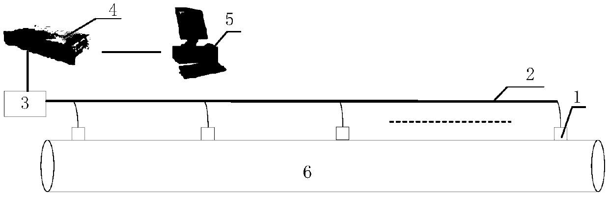
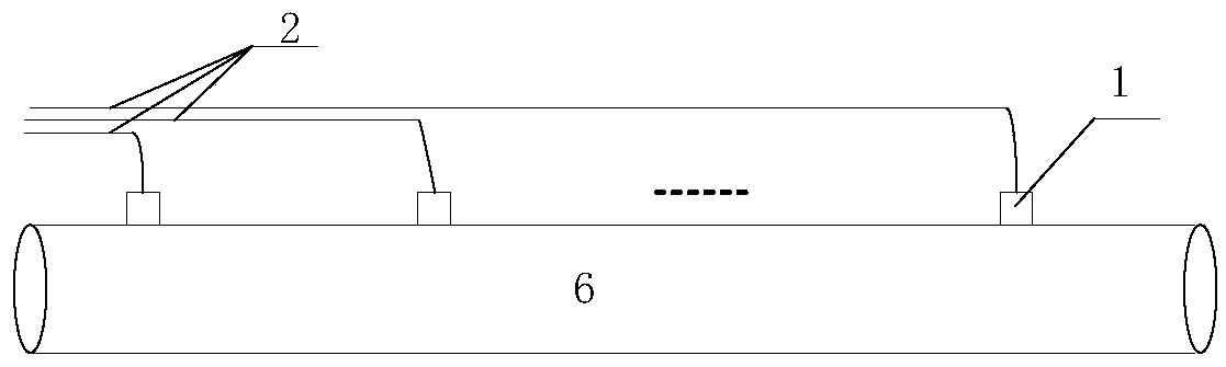
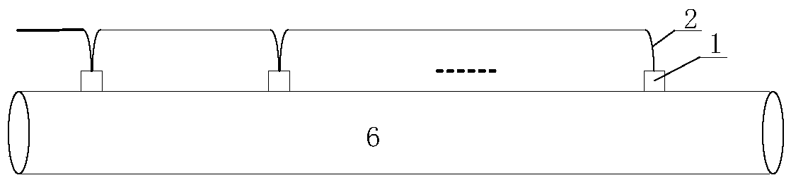
[0031] figure 1 It is a structural schematic diagram of the oil and gas pipeline leakage monitoring and positioning system based on optical fiber negative pressure waves of the present invention, the positioning system includes at least two fiber grating pressure sensors 1, and the fiber grating pressure sensors 1 are respectively installed at preset positions of the oil and gas pipeline; The fiber grating pressure sensor 1 is used to perceive the negative pressure wave signal inside the oil and gas pipeline 6, convert the negative pressure wave signal into an optical signal, and transmit the received negative pressure wave signal inside the oil and gas pipeline 6 through the communication optical cable 2 and the splitter 3 The signal is transmitted to the fiber grating fast demodulator 4, and the fiber grating fast demodulator 4 realizes the synchronous and ...
PUM
 Abstract
Description
Claims
Application Information