A holey core photonic crystal fiber with nano-air holes for light transmission

A photonic crystal fiber, air hole technology, applied in cladding fiber, optical waveguide light guide, microstructure fiber, etc., can solve the problems of high loss, no light intensity distribution in the central air hole, and light intensity reduction, etc.

Active Publication Date: 2019-05-03
东方光源集团有限公司
View PDF5 Cites 0 Cited by
  • Summary
  • Abstract
  • Description
  • Claims
  • Application Information

AI Technical Summary

Problems solved by technology

[0005] The conduction characteristics of these solid-core fibers have been studied a lot, but the conduction characteristics of hollow-core fibers are less
Initially, the transmission of light in low-refractive-index materials is due to the electric field difference at the interface between two materials with a large refractive index difference, but its loss is relatively high, and it can only be applied within a few centimeters.
On the other hand, the hollow-core photonic bandgap fiber can transmit light in the air core, and the loss is very low, but this kind of fiber can only transmit light of a specific wavelength, and the air core is relatively large (about 10 μm), resulting in a decrease in light intensity , which limits its application
K.Saitoh from Japan and B.Kibler from France theoretically simulated the transmission characteristics of a photonic crystal fiber with a tiny air hole in the center of the fiber core, and obtained that this fiber has the characteristics of flat dispersion, low loss, and small mode field area. It has application value in dispersion control, optical soliton transmission and nonlinearity, but this kind of fiber only transmits light through the quartz material in the fiber core, and the central air hole has no light intensity distribution
[0006] Solid-core photonic crystal fibers can transmit strong light for long distances in a tiny core, but when the core diameter is further reduced, light transmission in the waveguide is finally limited by diffraction, which scatters light from the high-refractive-index core go out

Method used


Image

  • A holey core photonic crystal fiber with nano-air holes for light transmission
  • A holey core photonic crystal fiber with nano-air holes for light transmission
  • A holey core photonic crystal fiber with nano-air holes for light transmission

Examples


Embodiment Construction

[0026] The present invention will be further described below in conjunction with accompanying drawing:

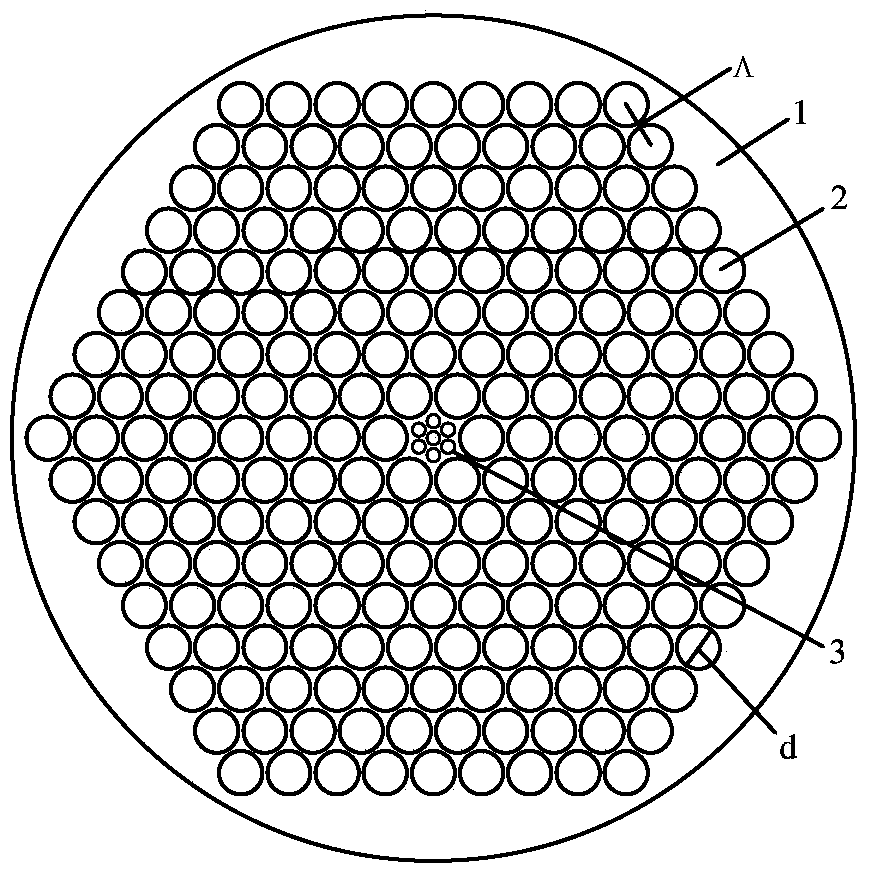
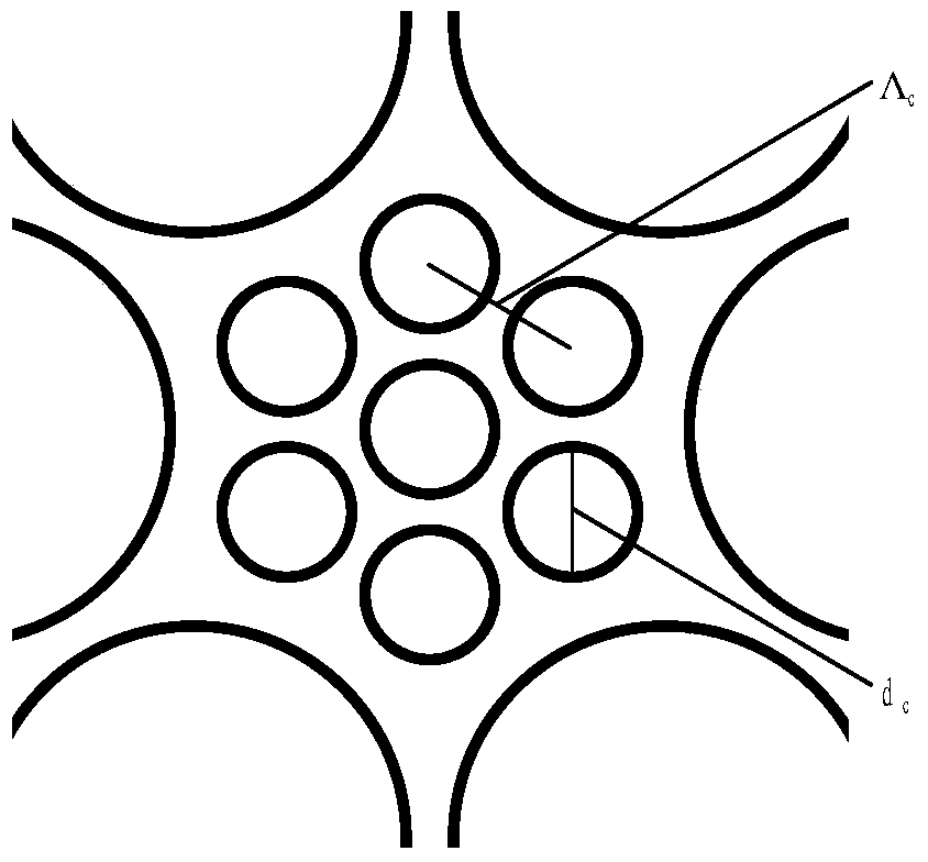
[0027] Such as figure 1 and 2 As shown, the optical fiber is composed of core air holes 3, cladding air holes 2, and matrix material 1; a columnar quartz matrix is ​​used as the matrix material, and at least one core air hole is processed in the center of the matrix material to form a core part; in the matrix material, the cladding air holes are processed around the core to form the cladding part, and the cladding air holes are processed according to the regular hexagonal multi-layer close arrangement structure, and the spacing of the cladding air holes is equal; the aperture of the cladding air holes It is larger than the aperture of the core air hole; the air filling rate of the core part is smaller than that of the cladding, and the equivalent refractive index of the core part is greater than that of the cladding.

[0028] The core part is to introduce 7 circular core ...


PUM


Abstract

A porous core photonic crystal optical fiber for transmitting light through nanometer air holes is composed of the fiber core air holes, the wrapping layer air holes and a base material. At least one fiber core air hole is machined in the center of the base material to form a fiber core part. The wrapping layer air holes are machined in the portion, around the fiber core part, of the base material to form a wrapping layer part. The wrapping layer air holes are machined according to a regular hexagonal multi-layer dense array structure, and the hole distances of the wrapping layer air holes are equal. The aperture of the wrapping layer air holes is larger than that of the fiber core air holes. The air filling rate of the fiber core part is smaller than that of a wrapping layer. The equivalent refractive index of the fiber core part is larger than that of the wrapping layer. The optical fiber has the advantages of low loss and wideband transmission, and the air holes have coherence and can be coupled with one another when light is tansmitted.

Description

technical field [0001] The invention relates to the technical field of hollow-core photonic crystal fibers, in particular to a porous-core photonic crystal fiber with nanometer air holes for light transmission. Background technique [0002] In traditional optical waveguides based on the principle of total internal reflection, it is impossible for light to travel long distances in low refractive index materials such as air. Although light transmission in low-refractive-index media can be achieved through the reflection of multi-layer media or photonic crystals, this structural fiber can only transmit specific wavelengths, and the large mode field area will lead to weakened light intensity. [0003] The emergence of photonic crystal fiber has injected new vitality into the research in the field of optics. It is a new type of optical fiber developed based on photonic crystal technology. The fiber core has a defect that destroys the periodicity of the cladding. This defect is u...

Claims


Application Information

Patent Timeline
Patent Type & Authority Patents(China)
IPC IPC(8): G02B6/02
CPCG02B6/02295
Inventor 赵兴涛王书涛刘晓旭王伟韩颖刘兆伦
Owner 东方光源集团有限公司
Why Eureka
Try Eureka