Laser illumination optical system combining diffraction optical element with laser

A diffractive optical element and laser lighting technology, which is applied in the field of optoelectronic communication, can solve problems such as unsatisfactory application fields, large size, and simple light field control method, and achieve high light intensity utilization efficiency, improved light utilization efficiency, and rich optical functions. Effect

Inactive Publication Date: 2016-04-20
JIAXING UPHOTON OPTOELECTRONICS TECH CO LTD
View PDF4 Cites 10 Cited by
  • Summary
  • Abstract
  • Description
  • Claims
  • Application Information

AI Technical Summary

Problems solved by technology

The traditional design method is to modulate the incident light field by means of refraction, occlusion, and imaging. The design method has complex optical elements, a large number, very low light utilization efficiency, and single function, which cannot realize complex lighting light fields. For example, traditional design methods cannot realize widely used light intensity distribution asymmetry correction and long-distance lighting above 1000 meters.
At the same time, the traditional lighting light field design method has large optical devices, high cost, and high requirements for the application environment. Fine dust on the surface of the optical device will cause serious defects in the special-shaped light field. The above factors have caused many problems for the use of this product. Unfavorable factors seriously limit the market application of the product
[0003] In modern technology, with the application and development of optoelectronic equipment and systems, the application of active light source lighting fields in various optoelectronic product fields is becoming more and more extensive, and the requirements are also constantly improving, such as night vision monitoring equipment, industrial lighting equipment, ultra-wide-angle The development of shooting equipment, ultra-long-distance shooting equipment and other fields has put forward com

Method used


Image

  • Laser illumination optical system combining diffraction optical element with laser
  • Laser illumination optical system combining diffraction optical element with laser
  • Laser illumination optical system combining diffraction optical element with laser

Examples


Embodiment Construction

[0021] The present invention will be described in further detail below in conjunction with the accompanying drawings, but it is not intended to limit the protection scope of the present invention.

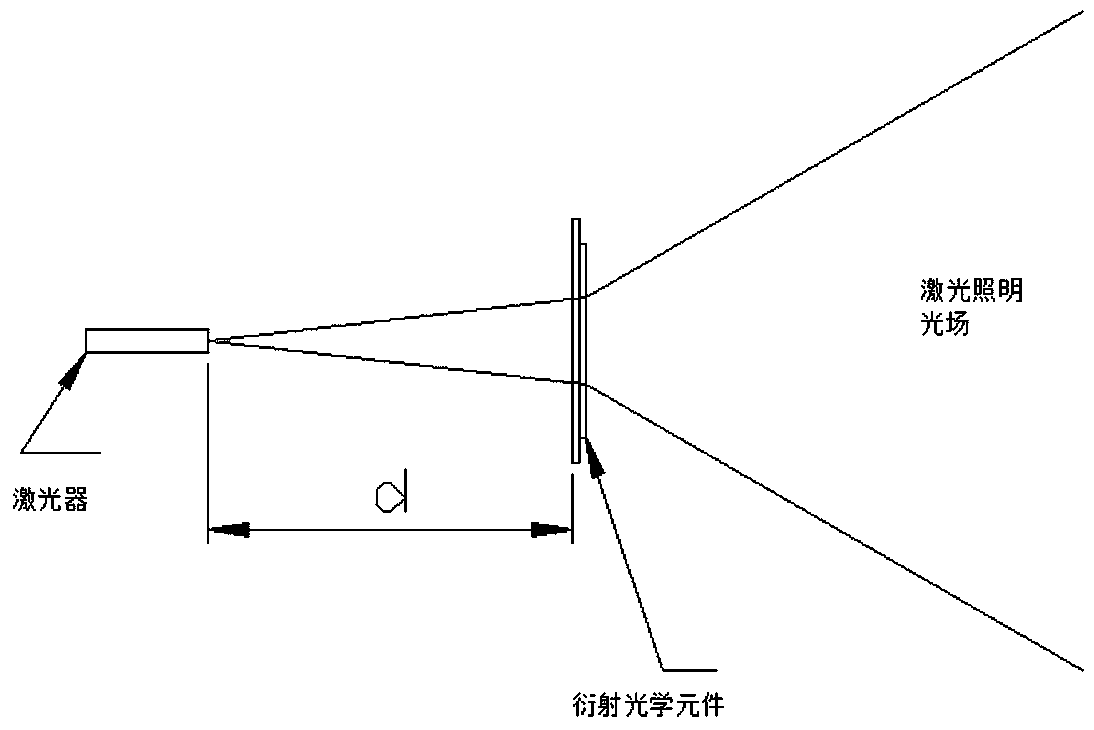
[0022] like figure 1 As shown, the function of the diffractive optical element is: the incident beam is a parallel or divergent laser beam, and the incident beam irradiates the diffractive optical element to realize an outgoing light field. The diffractive optical element is targeted according to the optical characteristics of the incident light field. Design, adjust the wavefront of the incident light field, and realize the Fourier transform from the incident light field to the required exit light field. The position of the laser light source and the diffractive optical element is fixed, and the divergence angle design of the required complex illumination light field can be realized only through the adjustment of one diffractive optical element. Cost, expanding the application fi...


PUM


Abstract

The invention belongs to the field of photoelectric communication, and especially relates to a laser illumination optical system combining a diffraction optical element with a laser. The laser illumination optical system comprises a laser irradiation light source and the diffraction optical element. After the laser irradiation light source is irradiated on the diffraction optical element, the optical field of the laser irradiation light source is optically modulated by the diffraction optical element, the laser optical field is spread along a specific angle area, and through design and adjustment of optical field wavefront phase modulation, micro morphology and overall dimension of the diffraction optical element, a divergence angle of a needed complex illumination optical field is designed. According to the invention, through diffraction optical design and optical modulation of optical field parameters of the laser irradiation light source are realized through the diffraction optical element, the light intensity utilization rate is high, the distribution shape of the optical field and the light intensity distribution can be flexibly controlled, and the complex illumination optical field can be realized according to needs of such application systems as monitoring shooting, human-eye observation and the like.

Description

technical field [0001] The invention belongs to the field of optoelectronic communication, and in particular relates to a laser illumination optical system which adopts a diffraction optical element combined with a laser. Background technique [0002] The optical design of the traditional lighting light field is based on the characteristics of light-emitting sources (such as LEDs, lasers, etc.), through the use of refractive optical components, such as lenses, mirrors, microlens arrays, lenses, astigmatism sheets, spatial light modulators (such as mask, liquid crystal screen, etc.), to realize the secondary modulation of the luminous light field, and to realize the output of the required lighting light field. The traditional design method is to modulate the incident light field by means of refraction, occlusion, and imaging. The design method has complex optical elements, a large number, very low light utilization efficiency, and single function, which cannot realize complex...

Claims


Application Information

Patent Timeline
IPC IPC(8): G02B27/09G02B27/42
CPCG02B27/0944G02B27/425
Inventor 贲宇尹晓东田克汉霍轶杰
Owner JIAXING UPHOTON OPTOELECTRONICS TECH CO LTD
Why Eureka
Try Eureka