
Hydraulic system cad collaborative design system and its construction method

A collaborative design system and hydraulic system technology, applied in the CAD network environment, computing, instruments, etc., can solve problems such as difficult information exchange, long development cycle, and increased cost, and achieve simplified client software, easy implementation, and low cost Effect

Active Publication Date: 2019-01-11
LIAONING UNIVERSITY OF TECHNOLOGY
View PDF3 Cites 0 Cited by
  • Summary
  • Abstract
  • Description
  • Claims
  • Application Information

AI Technical Summary

Problems solved by technology

[0012] (1) As far as the inherent essential characteristics of these software systems are concerned, they are developed with a single designer as the center, that is, they only support "human-computer" interaction, and are far from realizing the interaction between designers
[0013] (2) These software systems operate in the form of "automated islands", which can only achieve partial sharing of design data, and it is difficult to realize information exchange in heterogeneous environments, especially heterogeneous software, and the sharing of design information is poor
[0014] (3) The current CAD system and its analysis tools can only focus the designer's attention on a single specialty or single task in the design stage
In addition, the traditional product development technology cannot fully consider various factors in the product life cycle at the early stage of design, resulting in frequent design changes, resulting in long development cycles and increased costs, making it difficult to meet user needs
[0015] (4) From the perspective of man-machine environment integration, the traditional CAD system lacks the coordination and management of product design ideas, design process, design organization and design information, and also lacks collaborative support between people

Method used


Image

  • Hydraulic system cad collaborative design system and its construction method
  • Hydraulic system cad collaborative design system and its construction method
  • Hydraulic system cad collaborative design system and its construction method

Examples


Embodiment Construction

[0048] In order to make the objects and advantages of the present invention clearer, the present invention will be further described in detail below in conjunction with the examples. It should be understood that the specific embodiments described here are only used to explain the present invention, not to limit the present invention.

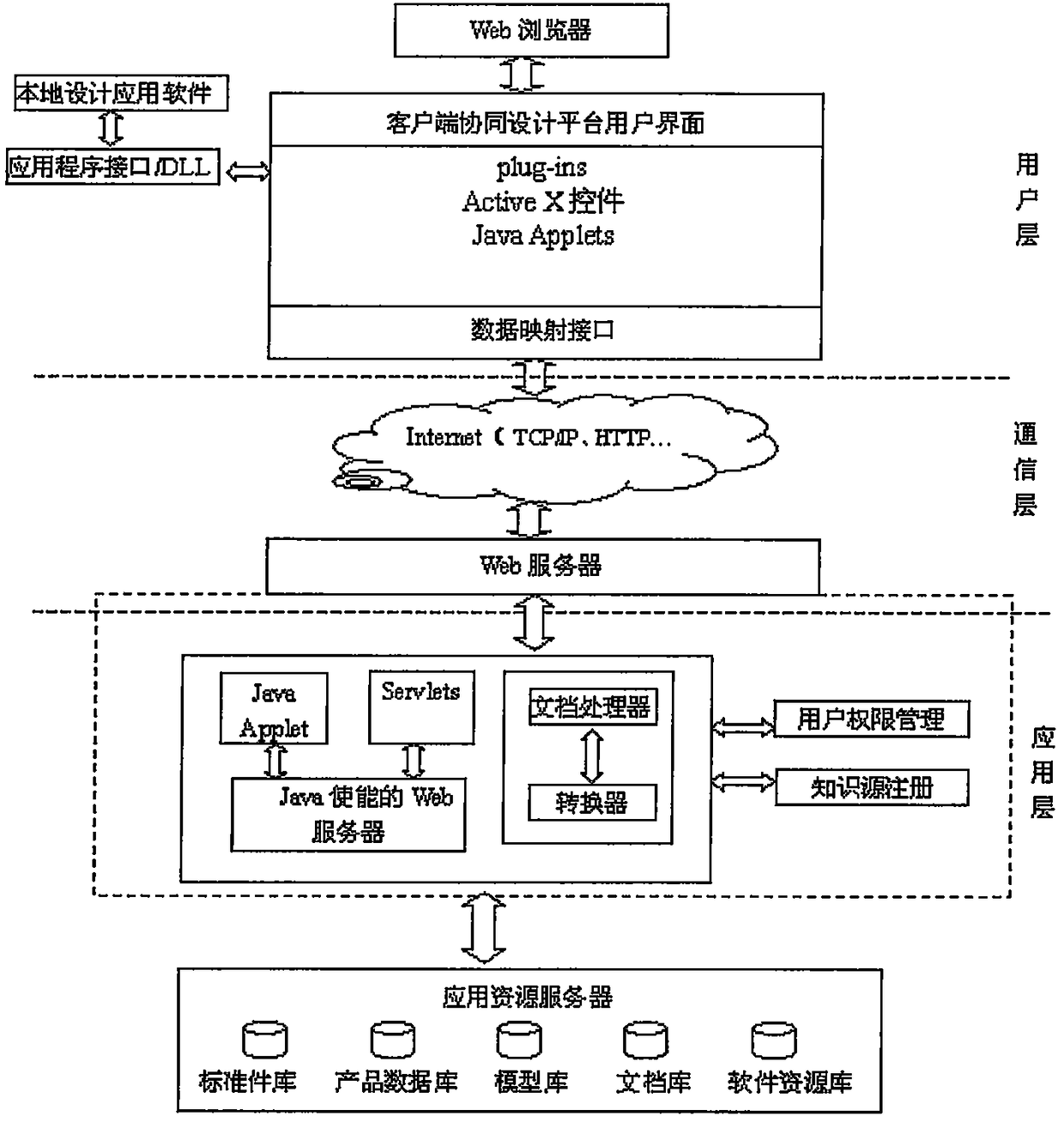
[0049] Such as figure 1 As shown, the embodiment of the present invention provides a hydraulic system CAD collaborative design system, including

[0050]The client uses a web browser with a plug-in, and the client program running on the client is the Java Applet code downloaded from the web server automatically by the web browser, which is used to provide human-computer interaction and human-to-human interaction interface and data mapping on the client side interface;

[0051] The middle layer, including the communication layer and the application layer, is a web server and an application server, responsible for receiving requests from local o...


PUM


Abstract

The invention discloses a hydraulic system CAD collaborative design system which comprises a client, a middle layer and a database server. A Web browser with plug-ins is adopted in the client, and the client is used for providing an interface for man-machine interaction and man-man interaction of the client and data mapping interfaces. The middle layer comprises a communication layer and an application layer and is responsible for receiving requests of a local or remote browser, driving an application layer of a server to process relevant data and then feed results back to the browser, and a most basic network communication function is provided for the whole system. An SQL Server database is used for the database server, and the database server is used for managing staff, text information, graphic information and various kinds of multimedia information. Original software resources of enterprises can be repeatedly used. Tool software used in cooperative design is the original software resources of the enterprises, and a new application system does not need to be developed again, so that the system is low in cost, short in period and easy to obtain. Client software is simplified, and the cross-platform problem is solved.

Description

technical field [0001] The invention relates to the field of design systems, in particular to a hydraulic system CAD collaborative design system and a construction method thereof. Background technique [0002] Internet-based collaborative design has no clear definition so far. We can think that Internet-based collaborative design technology is based on the computer-supported collaborative work environment, Internet and Web technology, CAD technology, multimedia technology, and the concept of concurrent engineering. , which aims to organize multidisciplinary experts across geographical and time barriers to achieve collaborative product design and development. [0003] Internet-based collaborative design is an effective application of CSCW technology in the process of product design and development. Facing the fierce market competition environment, how an enterprise can use teamwork and information technology to shorten the development cycle of its products, improve product q...

Claims


Application Information

Patent Timeline
Patent Type & Authority Patents(China)
IPC IPC(8): G06F17/50
CPCG06F30/00G06F2111/02
Inventor 李卫民
Owner LIAONING UNIVERSITY OF TECHNOLOGY
Learn More