Magnetic levitation compound molecular pump

A composite molecular pump and magnetic levitation technology, which is applied in the direction of pumps, pump control, pump components, etc., can solve the problems that the installation angle can only be vertical or horizontal, the molecular pump is difficult to achieve high speed, and the average trouble-free working cycle is short. Achieve the effects of simplifying the electrical control design, short trouble-free working period, and avoiding large rotor swing

Inactive Publication Date: 2016-04-27
TIANJIN EMAGING TECH
View PDF5 Cites 19 Cited by
  • Summary
  • Abstract
  • Description
  • Claims
  • Application Information

AI Technical Summary

Problems solved by technology

[0004] The existing molecular pumps all use traditional mechanical bearings. During the operation of traditional mechanical bearings, there is mechanical wear between the rotor and the stator. The higher the speed, the more serious the wear, and the service life of the bearings will be greatly reduced. Therefore, the molecular The pump is difficult to achieve high speed and the bearings need to be replaced regularly
At the same time, the mechanical bearings in the molecular pump need to be lubricated with oil or grease, and the backflow of oil vapor will pollute the vacuum chamber and affect the product quality
In addition, there is clearance in the mechanical bearing, and the rotor of the molecular pump swings a lot during operation, so the molecular pump has relatively large vibration and noise, short average trouble-free working period, and the installation angle can only be vertical or horizontal.

Method used


Image

  • Magnetic levitation compound molecular pump
  • Magnetic levitation compound molecular pump
  • Magnetic levitation compound molecular pump

Examples


Embodiment 1

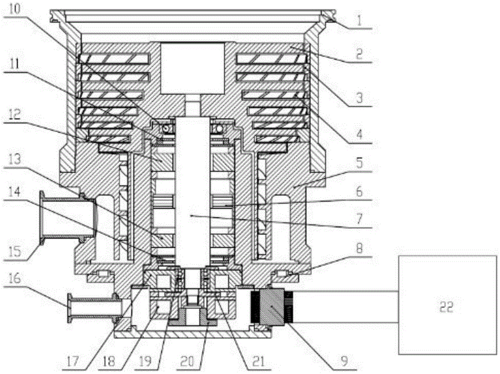
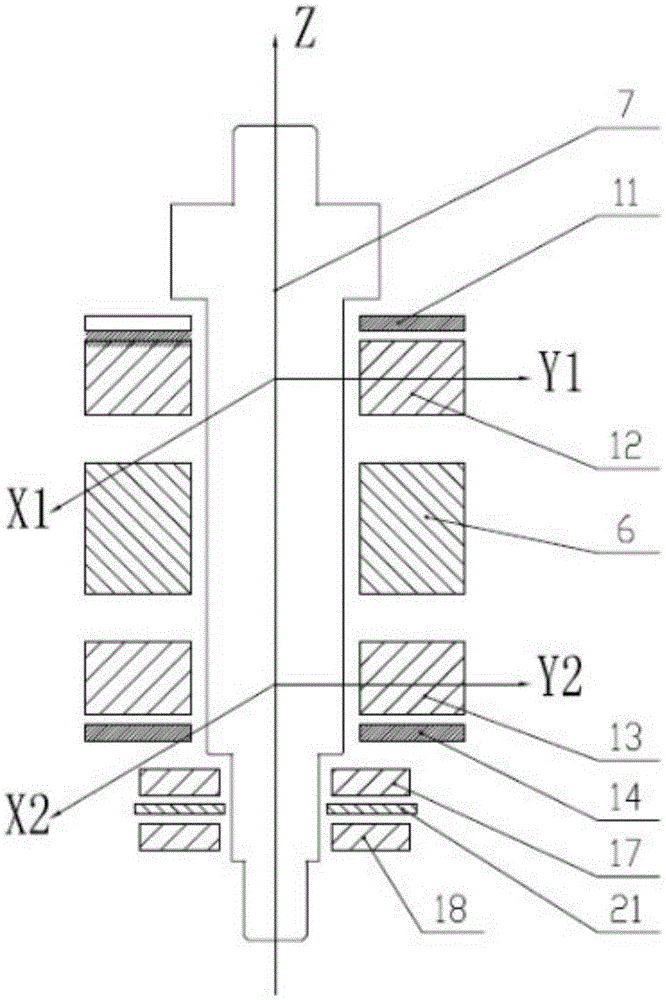
[0048] Embodiment 1: as figure 1 As shown, this embodiment consists of a pump casing 1, an impeller 2, a spacer ring 3, a static plate 4, a traction stage stator 5, a permanent magnet high-speed motor 6, a circulating water spacer ring 8, an air outlet flange 15, and a protective gas flange 16 , Upper protective bearing 10, lower protective bearing 19, five-degree-of-freedom magnetic suspension bearing, upper radial sensor 11, lower radial sensor 14, axial sensor 20, thrust plate 21 and controller 22.

[0049] The axial sensor 20 is arranged under the thrust plate 21 , and the spacer ring 3 is arranged between the impeller 2 and the pump casing 1 . The circulating water spacer ring 8 is arranged on the edge of the stator of the permanent magnet high-speed motor 6 , the air outlet flange 15 is arranged on the traction stage stator 5 , and the protective gas flange 16 is arranged on the base of the traction stage stator 5 .

[0050] The controller 22 is connected with the magne...

Embodiment 2

[0061] This embodiment is similar to embodiment 1, and its difference is:

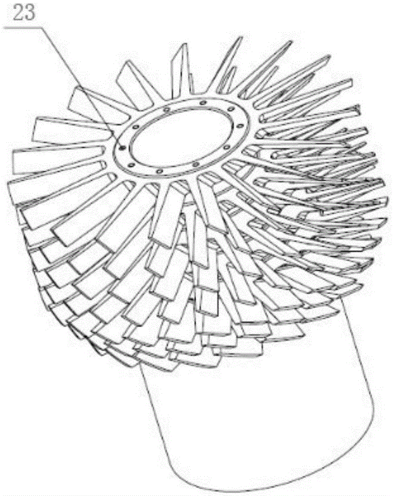
[0062] 1. The impeller 2 adopts an integral design, and high-strength alloy materials are selected to be formed by one-time milling by a multi-axis machining center; the blades of the impeller 2 adopt a variable-section design, and the upper end surface of the impeller 2 is provided with screw holes 23 uniformly distributed around the circumference for Regulates the unbalanced distribution of the mass of the rotor system.

[0063] 2, the control process of controller 22 is as follows:

[0064] S1. Automatically adjust the unbalanced vibration of the rotor system:

[0065] S11. When the electromagnetic main shaft 7 is in a static levitation state, extract and extract the same-frequency components of the control currents of the upper and lower radial magnetic bearings and the upper and lower shaft axial magnetic bearings respectively through the signal measurement circuit, and calculate the magnetic cen...


PUM


Abstract

The invention relates to a magnetic levitation compound molecular pump which comprises a pump casing, an impeller, spacer rings, stationary blades, a traction-level stator, a permanent magnet high-speed motor, an upper protection bearing, a lower protection bearing, a five-degree-of-freedom magnetic levitation bearing system and a controller. The magnetic levitation compound molecular pump adopts a turbine level and traction level combined design, has a wide pressure range (from 10<-6> Pa to 1 Pa), a high pumping speed, a high compression ratio and a high ultimate vacuum degree, and meets the using requirements of high vacuum and ultrahigh vacuum application industries. meanwhile, the magnetic levitation compound molecular pump adopts a five-degree-of-freedom magnetic levitation bearing, is free of mechanical contact, can achieves a high rotational speed, and has the advantages of no mechanical abrasion, low energy consumption, low noise, long service life, no need for lubrication, no oil stain and the like.

Description

technical field [0001] The invention relates to a molecular pump, in particular to a magnetic suspension composite molecular pump. Background technique [0002] Molecular pump is a mechanical turbine type vacuum obtaining equipment designed according to the law of molecular motion, which can obtain ultra-high vacuum. It is a necessary equipment for accelerators, electron colliders, lasers and other systems, and has a wide range of applications. The pumping mechanism is that in the molecular flow area, the surface of the rigid body moving at high speed transfers momentum to the gas molecules, so that the gas molecules generate directional flow in the direction of motion of the surface of the rigid body, so as to achieve the purpose of pumping. From the pumping principle of the molecular pump, it is known that the rotor blades of the molecular pump must have a linear velocity close to the speed of the gas molecules. Only with such a high speed can the gas molecules collide wit...

Claims


Application Information

Patent Timeline
Patent Type & Authority Applications(China)
IPC IPC(8): F04D19/04F04D27/00F04D29/058F04D29/66
CPCF04D19/048F04D27/00F04D29/058F04D29/668
Inventor 项海铭洪申平沙宏磊俞天野
Owner TIANJIN EMAGING TECH
Why Eureka
Try Eureka