
Photoionization detector

A photoionization and detector technology, applied in the field of gas chromatographic analysis instruments, can solve problems affecting the background noise of the detector, baseline size and baseline drift, reduce the sensitivity of the PID detector, reduce the efficiency of electron capture, etc., to reduce the electron recombination rate , Improve detection sensitivity, reduce the effect of secondary ionization

Inactive Publication Date: 2016-04-27
INST OF ELECTRONICS CHINESE ACAD OF SCI
View PDF7 Cites 2 Cited by
  • Summary
  • Abstract
  • Description
  • Claims
  • Application Information

AI Technical Summary

Problems solved by technology

However, since environmental samples generally contain water vapor, and moisture has a great impact on the detection sensitivity of the PID detector, it will reduce its sensitivity by 1-2 orders of magnitude. Therefore, how to remove the water vapor in the sample is the preparation of the PID detector. an important factor
In addition, in the PID detector, the electromagnetic interference generated by the driving power supply of the vacuum ultraviolet lamp will seriously affect the background noise, baseline size and baseline drift of the detector.
[0004] In the existing photoionization detector, there are great disadvantages in terms of noise reduction and moisture removal in the sample
In addition, when the metal electrode is irradiated by ultraviolet light, it will produce a photoelectric effect, and the collector is the most affected. When the traditional PID detector shields the collector, it generally compensates by sacrificing the distance between the collector and the emitter. However, if the distance is too large, it will reduce the electron capture efficiency and increase the electron recombination efficiency, thereby reducing the sensitivity of the PID detector.

Method used


Image

  • Photoionization detector
  • Photoionization detector
  • Photoionization detector

Examples


Embodiment 1

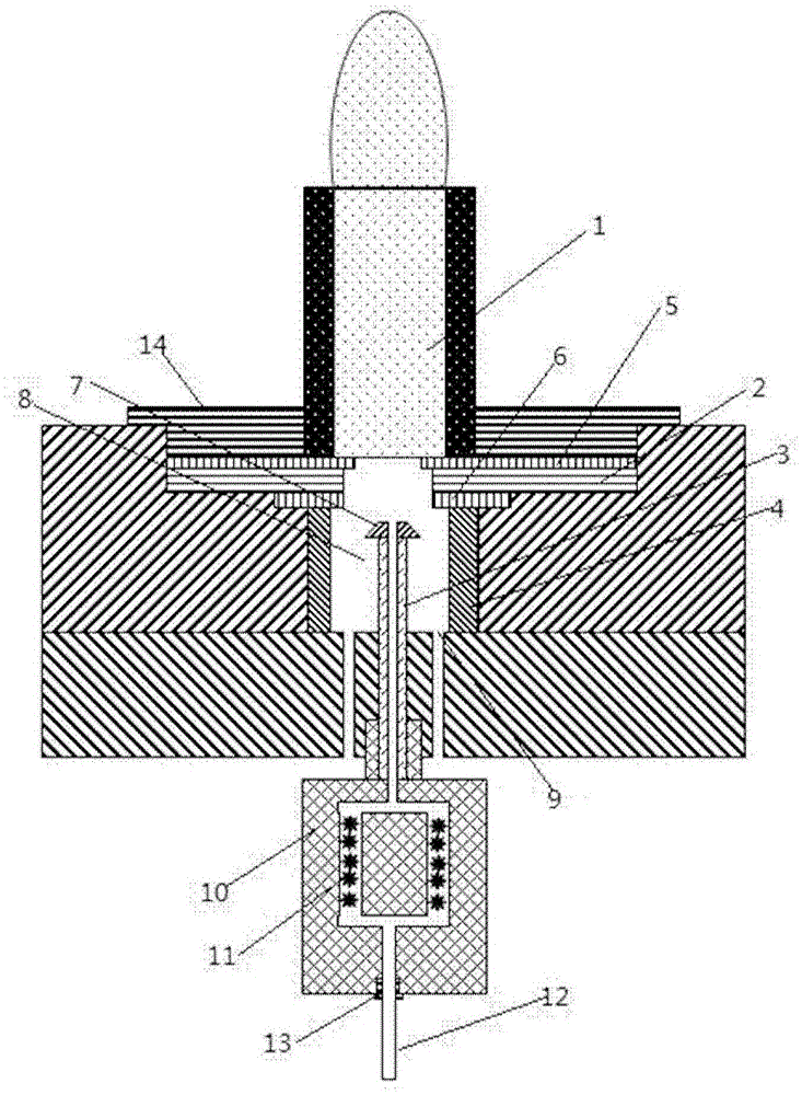
[0041] Such as figure 1 As shown, a photoionization detector integrated with a dehumidifier, the detector includes: a vacuum ultraviolet lamp 1 with an outer diameter of 6 mm, an ionization chamber 8, an emitter 3, a collector 4, a ground electrode 2, an insulating cap 7, a chromatographic Column 12, permeable exhaust gas outlet 9 and ultraviolet lamp drive power supply. The upper and lower ends of the detector are respectively fixed by the first pressure ring 13 and the second pressure ring 14 .

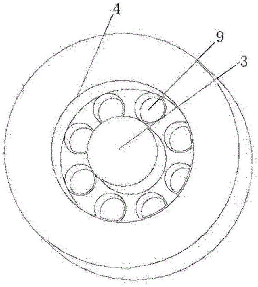
[0042] Wherein, the ground electrode 2, the collector 4, the emitter 3 and the insulating cap 7 are on the same axis, the ground electrode 2 shields the electromagnetic noise of the driving circuit of the vacuum ultraviolet lamp 1, and the emitter 3 is located on the axis of the collector 4, and is connected to the collector 4 are arranged in parallel and the distance between them is 0.1-1mm.

[0043] The emitter 3 adopts a cylindrical structure, and its preparation material is st...


PUM

PropertyMeasurementUnit
diameteraaaaaaaaaa
diameteraaaaaaaaaa
diameteraaaaaaaaaa

Abstract

A photoionization detector comprises an ionization chamber and an ultraviolet lamp, wherein an emitting electrode and a collecting electrode are arranged in the ionization chamber and are coaxially arranged, and the collecting electrode is a hollow cylinder body and surrounds the emitting electrode; a grounding electrode is further arranged between the emitting electrode and the ultraviolet lamp in the ionization chamber for shielding external electromagnetic interference. According to a three-electrode structure, the grounding electrode is mainly used for shielding electromagnetic interference of a driving power supply and the environment; with the design of the parallel structure of the collecting electrode and the emitting electrode, the distance between the collecting electrode and the emitting electrode is greatly reduced to 0.2-1 mm from 2-3 mm in a traditional structure, one-time electron capture efficiency is improved, and the detection sensitivity is greatly improved.

Description

technical field [0001] The invention relates to a gas chromatography analysis instrument, and further relates to a photoionization detector (PID). Background technique [0002] In the rapid detection of on-site gases such as ambient air quality monitoring, equipment internal environment monitoring, industrial pollution, chemical leakage, and chemical warfare agent diagnosis, a large number of high-sensitivity micro-detectors are required to achieve on-site analysis or online monitoring. [0003] Among the gas detectors, the photoionization detector has the characteristics of wide detection range, low detection limit and fast analysis speed. It is a very important and widely used detector in the field of chromatography. However, since environmental samples generally contain water vapor, and moisture has a great impact on the detection sensitivity of the PID detector, it will reduce its sensitivity by 1-2 orders of magnitude. Therefore, how to remove the water vapor in the sam...

Claims


Application Information

Patent Timeline
Patent Type & Authority Applications(China)
IPC IPC(8): G01N27/64
CPCG01N27/64
Inventor 孙建海马天军
Owner INST OF ELECTRONICS CHINESE ACAD OF SCI
Learn More