
Graphical microstructure of light emitting diode substrate

A light-emitting diode and graphic technology, which is applied in the direction of electrical components, circuits, semiconductor devices, etc., can solve the problems of reducing luminous brightness, reducing the internal quantum efficiency of light-emitting diodes, and high density, so as to achieve the effect of improving light extraction efficiency

Inactive Publication Date: 2016-04-27
GENESIS PHOTONICS
View PDF5 Cites 0 Cited by
  • Summary
  • Abstract
  • Description
  • Claims
  • Application Information

AI Technical Summary

Problems solved by technology

[0003] Taking the conventional light-emitting diode with Group-III nitride as an epitaxial structure as an example, an n-type semiconductor layer, a light-emitting structure layer, and a p-type semiconductor layer are stacked sequentially on a substrate, and in order to improve the device’s For the effect of current spreading and improving the light extraction efficiency, a transparent conductive layer, such as indium tin oxide (ITO), etc. is generally arranged on the p-type semiconductor layer; finally, the p-type semiconductor layer and the n-type semiconductor layer are respectively arranged There is a p-type electrode and an n-type electrode, and the p-type electrode and the n-type electrode are respectively arranged on the p-type semiconductor layer and the n-type semiconductor layer in ohmic contact; in an ideal light-emitting diode, when the light-emitting structure layer After the carriers are recombined into photons, if all these photons can be radiated to the outside world, the luminous efficiency of the light-emitting diode will be 100%. 100% luminous efficiency spreads to the outside world; for example, light-emitting diodes will cause misfit dislocation defects due to the strain generated by the lattice mismatch between the substrate and the epitaxial film, and some misfit dislocation defects It will also extend to the crystal surface, which is called a threading dislocation defect; for example, there is about 16% lattice mismatch between the sapphire substrate and the gallium nitride film, which is easy to cause the nitrogen grown on the aluminum oxide substrate. The high defect density of gallium chloride film leads to poor crystal quality of the light-emitting structure layer, which reduces the internal quantum efficiency of the light-emitting diode, thereby reducing its luminous brightness and generating heat, which increases the temperature of the light-emitting diode, thereby affecting the luminous efficiency; To effectively improve the luminous efficiency of light-emitting diodes, one of the inventors once applied for "patterned substrates and light-emitting diode elements with convergent light-emitting angles" on April 24, 2012, Taiwan Province of China Patent Publication No. 201345003, which discloses a A method of changing the direction of light and converging the light output angle through a plurality of strips on the surface of the substrate to increase the directivity of light and improve the light extraction efficiency of the light-emitting diode element, mainly through the plurality of strips on the surface of the substrate to improve the traditional substrate. The phenomenon of dislocation and dislocation caused by the lattice mismatch between epitaxial films can also guide the light transmitted laterally between the n-type semiconductor layer and the p-type semiconductor layer as forward light, so that the light can be emitted forward LED elements, and converging the light emission angle to 100-110 degrees, not only has better directivity, but also can avoid the emitted light from being absorbed by adjacent light-emitting diode elements, thereby greatly improving the light extraction efficiency; however, after the present invention Many times of experiments and researches, the size and shape of the patterned structure formed by the plurality of strips on the substrate have not reached the optimization of improving the luminous efficiency. Therefore, the inventors believe that the light emitting diode There is still room for adjustment and improvement in efficiency

Method used


Image

  • Graphical microstructure of light emitting diode substrate
  • Graphical microstructure of light emitting diode substrate
  • Graphical microstructure of light emitting diode substrate

Examples


Embodiment Construction

[0029] The purpose of the present invention and its structural design and functional advantages will be described based on the preferred embodiments shown in the following figures, so that the examiners can have a more in-depth and specific understanding of the present invention.

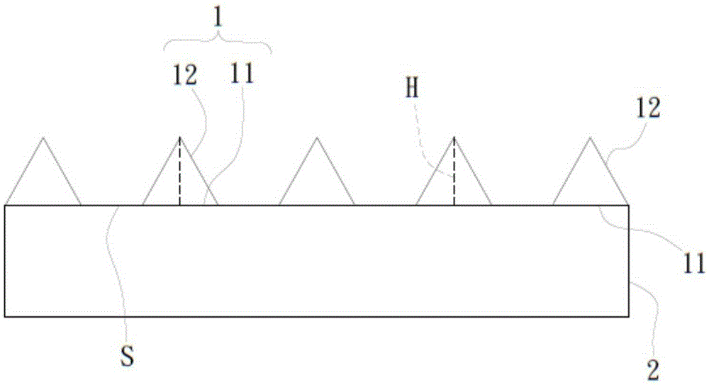
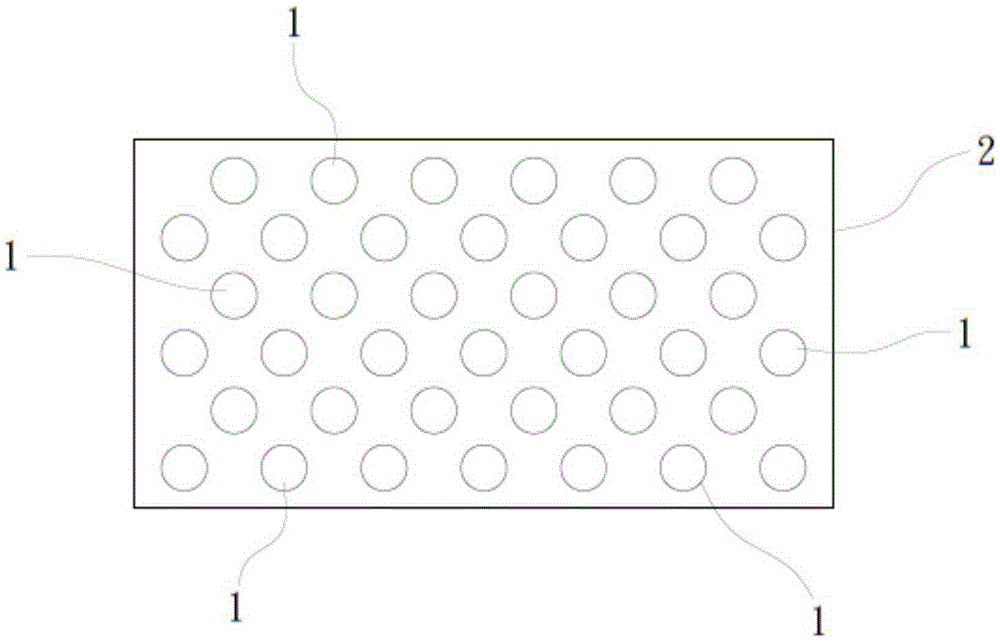
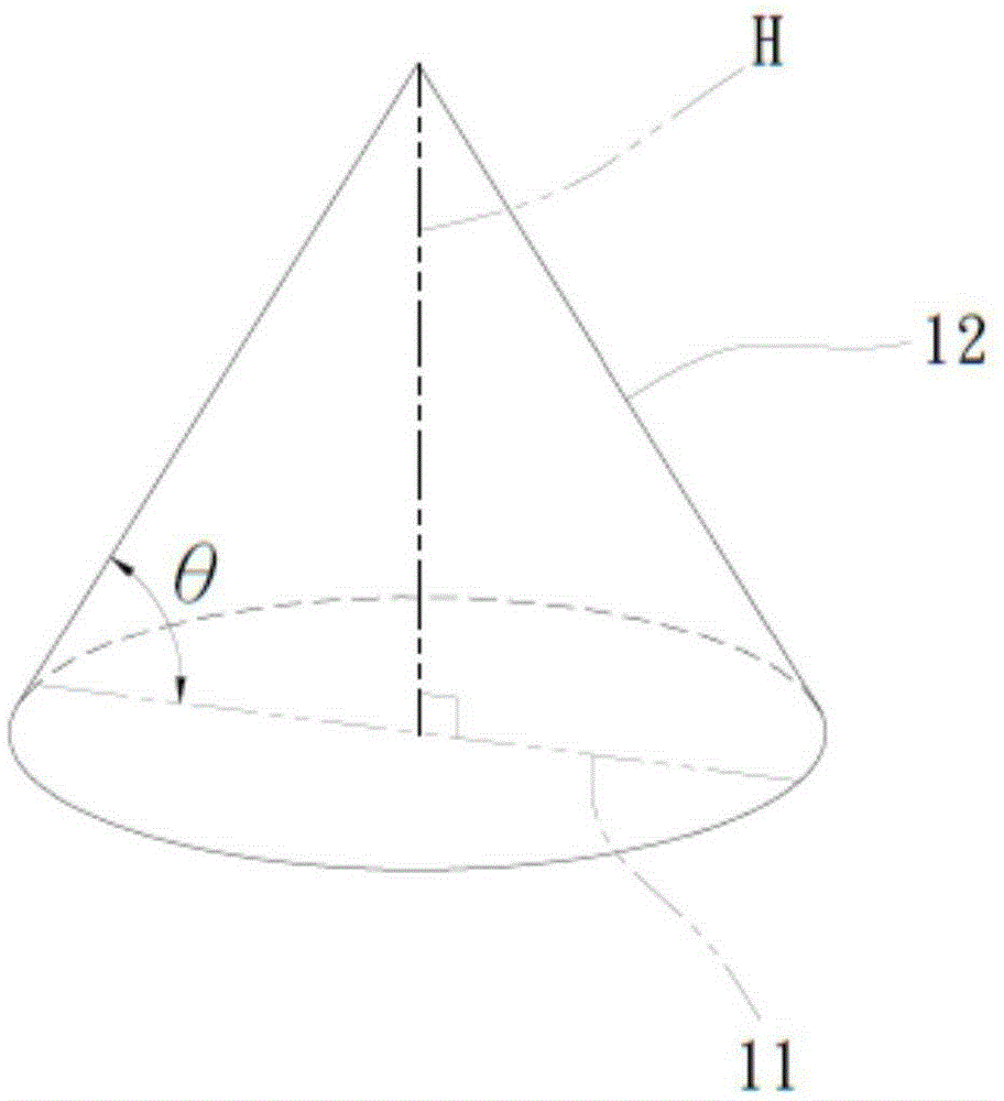
[0030] first, figure 1 It is a schematic cross-sectional view of the patterned microstructure of a preferred embodiment of the patterned microstructure of the light-emitting diode substrate of the present invention; figure 2 It is a top view of the patterned microstructure of a preferred embodiment of the patterned microstructure of the light-emitting diode substrate of the present invention; image 3 It is a schematic diagram of a single patterned microstructure of a preferred embodiment of the patterned microstructure of the light-emitting diode substrate of the present invention; such as Figure 1-3 Shown are a schematic cross-sectional view of the patterned microstructure, a top view of the pa...


PUM


Abstract

The invention relates to a patterned microstructure of a light emitting diode (LED) substrate. The substrate is provided with patterned microstructures arranged in an array. Each patterned microstructure includes a bottom surface and a lateral surface adjacent to the bottom surface. There is an angle [theta] between the lateral surface and the bottom surface, where 0 DEG <[theta]<90 DEG . The length of the bottom surface ranges between 2.5 microns and 2.8 microns. An end of the lateral surface far away from the bottom surface is gradually shrunk into an intersection, and the height between the intersection and the bottom surface ranges between 1.5 microns and 1.9 microns. Accordingly, the invention can effectively achieve improving light extraction efficiency of the LED by optimizing the size of the patterned microstructure cyclically and alternately arranged on the LED substrate.

Description

technical field [0001] The present invention relates to a patterned microstructure of a light-emitting diode substrate, in particular to a patterned microstructure formed on a light-emitting diode substrate. The size of the patterned microstructure can effectively improve the light extraction efficiency of the light emitting diode. Background technique [0002] Compared with traditional incandescent light sources, light emitting diodes (LED) have the advantages of power saving, small size, low voltage drive, no mercury, no thermal radiation, fast operation response, and long life. Light emitting diodes are the next generation The best light source for energy-saving lighting has been widely used in lighting fields such as household indicator lights, backlights of liquid crystal displays, graphic display screens or third brake lights of automobiles, including resonant-cavity light emitting diodes (RCLEDs), Vertical-cavity surface-emitting diodes (VCSEDs) and semiconductor lig...

Claims


Application Information

Patent Timeline
Patent Type & Authority Applications(China)
IPC IPC(8): H01L33/22H01L33/32
CPCH01L33/22H01L33/32H01L33/10H01L33/12
Inventor 陈正彬
Owner GENESIS PHOTONICS
Learn More