Forward-backward drawing and forming method for metal plate soft mould

A metal sheet, reverse deep drawing technology, applied in metal processing equipment, forming tools, manufacturing tools, etc., can solve the problems of complex mold structure, surface quality and precision limitations of formed products, etc., to reduce bending deformation resistance, prevent internal wrinkles Effect

Active Publication Date: 2016-05-04
YANSHAN UNIV
View PDF7 Cites 16 Cited by
  • Summary
  • Abstract
  • Description
  • Claims
  • Application Information

AI Technical Summary

Problems solved by technology

However, at present, the positive and negative deep drawing forming method is generally common in the traditional rigid die deep drawing forming. Although it

Method used


Image

  • Forward-backward drawing and forming method for metal plate soft mould
  • Forward-backward drawing and forming method for metal plate soft mould
  • Forward-backward drawing and forming method for metal plate soft mould

Examples


Embodiment 1

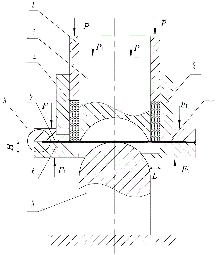
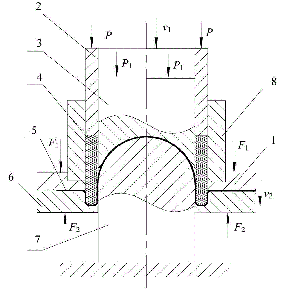
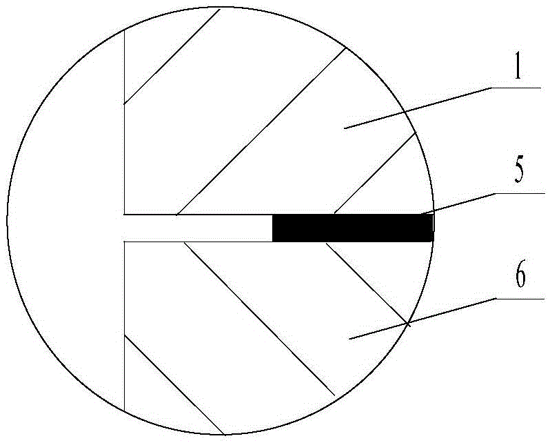
[0030] exist figure 1 In the schematic diagram of the front view section of the mold device before processing of the metal sheet soft mold front and back deep drawing forming method shown, the mold has a cylindrical punch 7 whose lower end is fixed on the forming equipment, and its upper end is shaped as a positive spherical surface. A lower binder ring 6 is set on the outside of the punch, and the lower binder ring is a ring, and the diameter of the central through hole is greater than or equal to the outer diameter of the punch. The circular groove of L is called deep drawing groove. A corresponding upper blankholder 1 is arranged on the lower blankholder, which is also a circular ring, and the diameter of its central through hole = diameter of the punch + width L of the deep drawing groove of the lower blankholder. The central through hole of the binder ring is also provided with an annular groove, which is a connecting groove, and the connecting groove is provided with a ...

Embodiment 2

[0033] exist Figure 4 In the schematic diagram of the front view section of the mold device before the processing of the metal sheet soft mold front and back deep drawing forming method shown, the mold has a cylindrical punch 7 whose lower end is fixed on the mold fixing device, and its upper end is in the shape of a truncated cone. A lower binder ring 6 is set on the outside of the punch, and the lower binder ring is a ring, and the diameter of the central through hole is greater than or equal to the outer diameter of the punch. The circular groove of L is called deep drawing groove. A corresponding upper blankholder 1 is arranged on the lower blankholder, which is also a circular ring, and the diameter of its central through hole = diameter of the punch + width L of the deep drawing groove of the lower blankholder. The central through hole of the binder ring is also provided with an annular groove, which is a connecting groove, and the connecting groove is provided with a ...


PUM


Abstract

The invention discloses a forward-backward drawing and forming method for a metal plate soft mould. A lower drawing ring is arranged on the outer surface of a male mould of a mould device in a sleeving mode; a drawing slot is formed in the lower drawing ring; an upper drawing ring is arranged on the upper surface of the lower drawing ring; a charging barrel is arranged on the upper drawing ring; a force-reducing column is arranged in the charging barrel; a pressure head is arranged between the force-reducing column and the charging barrel; and the lower end of the force-reducing column is a concave surface which corresponds to the male mould. The forming method is mainly characterized in that the upper and the lower drawing rings are oppositely pressed by external force; a solid particle medium is put into a ring-shaped cavity, the pressure head descends at a speed of v1, and the particle medium is compressed to carry out forward drawing deformation on the plate; meanwhile, under the action of back pressure P1, the force-reducing column is always in a contact state with the plate, the pressure head continuously descends, and the upper and the lower drawing rings float along with the pressing of the pressure head, wherein a flotation speed is smaller than a pressing speed of the pressure head. According to the invention, by combining solid particle medium soft mould forming and backward drawing into one set of mould, the invention provides the forward-backward drawing and forming method for the metal plate soft mould which is simple in structure, is energy-saving and environmentally-friendly, and is formed once.

Description

technical field [0001] The invention relates to a processing method of a metal plate, in particular to a deep drawing forming method. Background technique [0002] In order to meet the development needs of automobile, aviation, aerospace, electronics and other industries, metal sheet forming processes such as soft mold forming and reverse drawing have emerged. The emergence of these processes has promoted the development of sheet metal forming technology. The soft mold forming process mainly includes hydroforming with water or oil as the force transmission medium, viscous medium forming with viscous material as the force transmission medium, and rubber soft mold forming with elastomer rubber as the force transmission medium. However, due to the disadvantages of the medium used in the hydraulic (viscous medium) forming process, such as poor high temperature resistance, difficult sealing, and pollution once ruptured, the large-scale application of this process in production is...

Claims


Application Information

Patent Timeline
IPC IPC(8): B21D22/22B21D37/10
CPCB21D22/22B21D37/10
Inventor 赵长财贾向东曹秒艳董国疆杜冰
Owner YANSHAN UNIV
Why Eureka
Try Eureka