Prebaking aluminum cell anode set structure

An aluminum electrolytic cell and anode group technology, which is applied in the field of aluminum electrolytic anodes, can solve the problems of fluctuating working conditions of electrolytic cells, pollution, uneven conductivity of carbon electrodes, etc., and achieve the effects of fast and convenient connection process, tight connection, and cost reduction.

Active Publication Date: 2016-05-04
周俊和 +1
View PDF8 Cites 7 Cited by
  • Summary
  • Abstract
  • Description
  • Claims
  • Application Information

AI Technical Summary

Problems solved by technology

[0005] At present, the traditional way to deal with the anode residues is to smash and fall off the residues connected to the conductive rods in the anode assembly workshop, and then use the aluminum conductive rods after the broken anode steel bowls cast by phosphorus pig iron to be used in new ones. The carbon block is recycled in this way, which results in time-consuming and laborious replacement process of the carbon block
[0006] And under normal circumstances, the production of anode residues is 10-15% of the output of aluminum ingots, resulting in a great waste. According to the current annual production of 26-27 million tons of electrolytic aluminum in my country, the anode residues are as high as 260-390 tons. 10,000 tons / year, according to the value of anode carbon block 2700 yuan / ton, the value of wasted anode carbon block reaches tens of billions of yuan every year, and the waste in the world is even more. Carbon itself has a porosity of 25-27%, and a large amount of electrolyte is adsorbed in the body of the residual electrode. The main component of the electrolyte is fluoride salt, and the anode residual electrode containing a large amount of fluoride salt is very serious to the environment.
[0007] When using the existing cast-type anode carbon block group, in order to reduce the waste of the residual electrode as much as possible, the residual electrode must be burned as thin as possible. At the end of the life of the anode carbon block, the top surface of the anode carbon block is very close to the electrolyte level, which is affected by the magnetic field and air flow. Affected by strong waves on the surface of the electrolyte, or due to production control deviations, in the actual production process, the anode steel claws are often corroded by the electrolyte, and the iron in the steel claws dissolves into the electrolyte, and then enters the aluminum water to affect the quality of the aluminum ingots. In actual production, the average lifespan of the steel claws used in the electrolysis workshop is only about 3 years, which also increases the production cost to a certain extent
And at the end of the life of the anode carbon block, the thickness of the too thin residual electrode will inevitably lead to uneven conduction of the carbon electrode, resulting in fluctuations in the working conditions of the electrolytic cell and increased electrical loss
[0008] Cast steel claw-carbon block connection method, the contact voltage drop of the connection surface is relatively large, the temperature of the poured phosphorus pig iron molten iron is about 1600 ℃, after cooling, there must be a gap between the phosphorus pig iron bowl and the carbon bowl, so the steel claw carbon When the block anode group works in the electrolytic cell, a voltage drop of about 150mv occurs between the steel claw and the contact surface of the carbon block, resulting in an electrical loss of about 400-500 degrees / ton of aluminum

Method used


Image

  • Prebaking aluminum cell anode set structure
  • Prebaking aluminum cell anode set structure

Examples


Embodiment

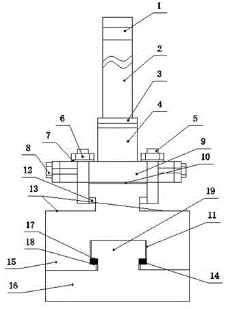
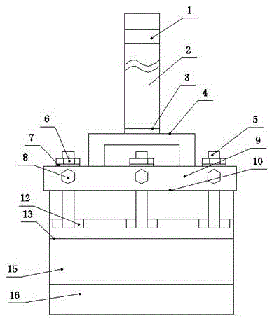
[0026] Embodiment: a kind of prebaked aluminum electrolytic cell anode group structure, as attached Figure 1-2As shown, the mechanical steel claw bottom plate 9 is included, and the mechanical carbon block connection part is provided under the mechanical steel claw bottom plate 9, and the new anode carbon block 15 is connected to the bottom of the mechanical carbon block connection part, and the new anode carbon block 15 There is a T-shaped connection protrusion 19 on the upper part of the carbon block that is used in conjunction with the mechanical carbon block connection part. The T-shaped connection protrusion 19 on both sides of the upper part of the carbon block is provided with a T-shaped connection protrusion bearing shoulder 17. The bottom T-shaped connection groove 11 of the carbon block used in conjunction with the T-shaped connection protrusion 19 on the top of the carbon block is provided with a T-shaped connection groove hook bearing shoulder 18 at the bottom of t...


PUM


Abstract

The invention discloses a prebaking aluminum cell anode set structure which comprises a mechanical steel claw base plate. A connection portion of a mechanical steel claw and a carbon block is arranged below the mechanical steel claw base plate. A novel anode carbon block is connected to the portion below the connection portion of the mechanical steel claw and the carbon block. An upper carbon block T-shaped connection convex head is arranged on the novel anode carbon block. The two sides of the upper carbon block T-shaped connection convex block are provided with T-shaped connection convex head force-bearing shoulders. The bottom of the upper carbon block T-shaped connection convex head is provided with a lower carbon block T-shaped connection groove used in cooperation with the upper carbon block T-shaped connection convex head. The bottom of the lower carbon block T-shaped connection groove is provided with a T-shaped connection groove hook force-bearing shoulder. An old anode carbon block is connected to the portion below the novel anode carbon block. The prebaking aluminum cell anode set structure has the advantages that no residue anode is generated, the utilization rate of the anode carbon block is improved from 70-80% traditional to 100%, the production cost of electrolytic aluminum can be lowered, the service life of the steel claw is long, the working conditions of the electrolytic cell are stable, electrical losses are low, the novel anode carbon block and the old anode carbon block are rapidly and conveniently connected, heat energy is saved, connection is firm, and the electrical conduction effect is good.

Description

technical field [0001] The invention relates to an aluminum electrolytic anode, in particular to an anode group structure of a prebaked aluminum electrolytic cell. Background technique [0002] In the modern electrolytic aluminum industry, prebaked anodes are used to produce electrolytic aluminum. The prebaked anode is generally a cuboid with a stable geometric shape. It uses stone tar and pitch coke as the aggregate and coal tar pitch as the binder. It has different sizes according to the size of the electrolytic cell current and the process. Its current density Generally at 0.68-0.9A / cm 2 Within the range, the service life of each carbon block is generally 23-30 days. [0003] In the existing prebaked anode electrolytic aluminum production, the anode steel claws and the anode carbon block are all connected by casting of phosphorus pig iron, and there are 2-4 diameters of 160-180mm on the upper surface of the prebaked anode carbon block in the conductive direction, and th...

Claims


Application Information

Patent Timeline
Patent Type & Authority Applications(China)
IPC IPC(8): C25C3/12
CPCC25C3/125
Inventor 邹建明
Owner 周俊和
Why Eureka
Try Eureka