Fuel gas and EGR mixed direct injection system

A technology of gas and mixed gas, which is applied in the direction of charging system, exhaust gas recirculation, combustion engine, etc., to reduce the quantity, avoid response delay, and eliminate the effect of uneven division of each cylinder

Active Publication Date: 2016-05-04
DONGFENG COMML VEHICLE CO LTD
View PDF17 Cites 0 Cited by
  • Summary
  • Abstract
  • Description
  • Claims
  • Application Information

AI Technical Summary

Problems solved by technology

[0004] The purpose of the present invention is to provide a gas and EGR mixed direct injection system for the existing problems of EGR system delay and precise control of EGR quantity.

Method used


Image

  • Fuel gas and EGR mixed direct injection system

Examples


Embodiment Construction

[0015] The present invention will be further described in detail below in conjunction with the description of the drawings and the specific embodiments.

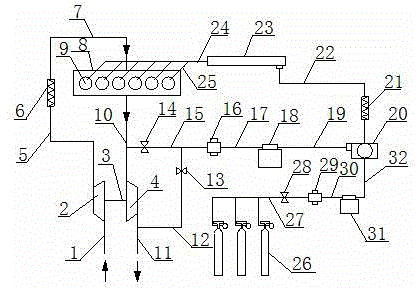
[0016] See figure 1 , A gas and EGR hybrid direct injection system, including compressor 2, turbine 4, intake air intercooler 6, engine 8, cylinder 9, low pressure EGR pipe 12, high pressure EGR pipe 15, EGR pump 18, mixer 20, The mixed gas rail 23, the mixed gas nozzle 25, the gas cylinder 26 and the gas pump 31. The inlet of the compressor 2 is connected to the inlet pipe 1, and the outlet of the compressor 2 is connected to the inlet of the inlet intercooler 6 through the compressor outlet pipe 5; the outlet of the inlet intercooler 6 passes through the inlet The gas main 7 is connected to the engine 8. The inlet of the turbine 4 is connected to the engine 8 through an exhaust manifold 10, and the outlet of the turbine 4 is connected to the exhaust pipe 11; the compressor 2 and the turbine 4 are connected through a connec...


PUM


Abstract

The invention discloses a fuel gas and EGR mixed direct injection system. A low-pressure EGR pipe is connected with an exhaust pipe and a high-pressure EGR pipe, a low-pressure EGR valve is installed on the low-pressure EGR pipe, and a high-pressure EGR valve is installed on the high-pressure EGR pipe; an inlet of an EGR pump is connected with an exhaust manifold through the high-pressure EGR pipe, and an outlet of the EGR pump is connected with an inlet in one end of a mixer through an air outlet pipe of the EGR pump; an outlet of a liquidation fuel gas vessel is connected with an inlet of a fuel gas pump through an air inlet pipe of the fuel gas pump, an outlet of the fuel gas pump is connected with an inlet in the other end of the mixer through an air outlet pipe of the fuel gas pump, an outlet of the mixer is connected with an inlet of a mixed gas track through a mixed gas track connecting pipe, an outlet of the mixed gas track is connected with a mixed gas nozzle through a mixed gas supply pipe, and the mixed gas nozzle is installed on a cylinder or in an air inlet channel close to the cylinder.

Description

technical field [0001] The invention relates to a direct injection system, more specifically to a gas and EGR mixed direct injection system, which belongs to the technical field of exhaust gas recirculation (EGR) and gas supply systems in the field of gas engines. Background technique [0002] At present, in the face of the increasingly severe environmental crisis, countries have increasingly stringent requirements for emission regulations, so reducing emissions has become the main direction for the development of internal combustion engines. Clean fuels represented by natural gas are gradually being valued. A large number of studies have shown that the emissions of gas engines using clean fuels are significantly lower than those of traditional gasoline and diesel engines. At the same time, clean fuels such as natural gas can alleviate my country's demand for oil to a certain extent as an alternative fuel. On the other hand, the EGR system is used to reduce the NO of the int...

Claims


Application Information

Patent Timeline
Patent Type & Authority Applications(China)
IPC IPC(8): F02M21/02F02M26/09F02M26/14F02M26/36F02M26/34F02M26/38
CPCF02M21/02F02M21/0218Y02T10/30
Inventor 徐敏程伟李智张宏飞安涛
Owner DONGFENG COMML VEHICLE CO LTD
Why Eureka
Try Eureka