PTC parallel flow heater

A heater and parallel flow technology, which is applied in the field of PTC parallel flow heaters, can solve the problems that the gap between the surface and the PTC element cannot fit well, the heat exchange efficiency decreases, and the thermal conductivity is small, so as to achieve easy industrial production and stable temperature , High heat exchange efficiency

Inactive Publication Date: 2016-05-04
WUHAN BUSINESS UNIV
View PDF8 Cites 0 Cited by
  • Summary
  • Abstract
  • Description
  • Claims
  • Application Information

AI Technical Summary

Problems solved by technology

[0003] At present, the common structure of the PTC liquid heater is composed of the heater body (heating chamber) and the PTC element chamber, which solves the problem of water and electricity separation heating, and the heating chamber uses a variety of structural forms, and the gap between its surface and the PTC element is relatively small. The large size cannot fit well, which affects the heat transfer; because the thermal conductivity of aluminum itself is smaller than that of copper, in order to increase the heat conduction area and flow time, the structure is often made into a multi-stroke method, so that the flow rate is fast and the heating time is short, requiring a large However, metal aluminum is easily oxidized when heated at high temperature for a long time, resulting in a decrease in heat transfer efficiency and increased energy consumption

Method used


Image

  • PTC parallel flow heater
  • PTC parallel flow heater
  • PTC parallel flow heater

Examples


Embodiment approach 1

[0047] In order to illustrate the beneficial effects of the PTC parallel flow heater of the present invention, the inventors of the present invention obtained the following relevant conclusions by means of experiments.

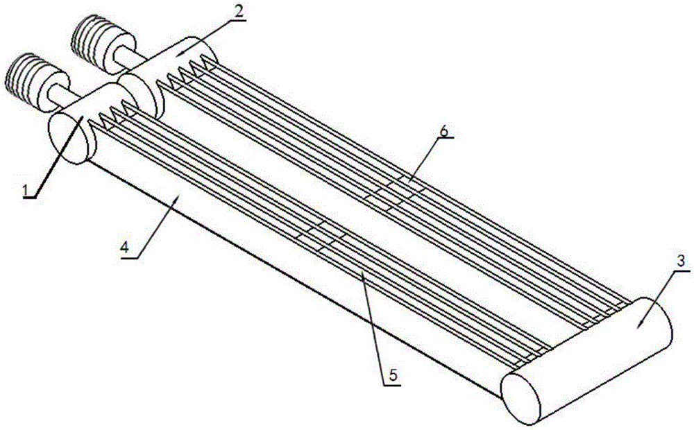
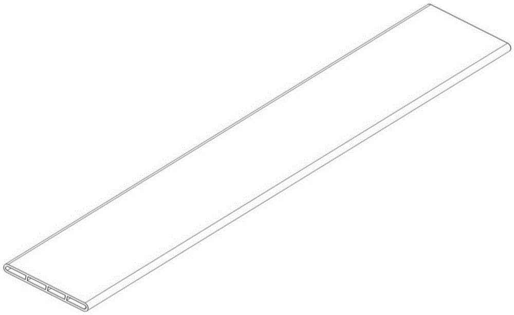
[0048] Test conditions: using such as figure 1 The heater body of the structure shown, and adopts such as Figure 5 The structural dimensions of the main body of the heater shown, the dimensions of the flat heat exchange tubes and their array layout refer to Figure 6 , Figure 6 for Figure 5 The A-A cross-sectional dimension drawing, Figure 5 and Figure 6 The unit of each dimension is mm, the flat heat exchange tube and the PTC element are fixed and compressed by screws, and the inlet and outlet ports are standard 4-point interface; the size of the PTC element is 100mm×21mm×5mm, a total of 14 pieces, each with a voltage of 220V and a power of 160W ; 220V small circulating water pump, pump head 8m, maximum flow 60L / min.

[0049] Comparative test piece...

Embodiment approach 2

[0053] In the floor low-temperature radiant heating system and radiator heating mode, the heating heat source is hot water at 55°C / 45°C, and the wall-hung boiler mainly uses natural gas, liquefied petroleum gas, city gas and electricity as energy sources. The patented PTC parallel heating system of the invention Flow liquid heater, high heat exchange efficiency, can replace wall-hung boilers that use electricity as energy consumption in floor low-temperature radiant heating systems (with electric heating tubes as the main method), and can achieve certain energy-saving benefits.

Embodiment approach 3

[0055] For instant electric water heaters, because of its excessive power (minimum power 4500W), many potential safety hazards will be caused during use. Using the PTC liquid heater of the present invention, the separation of water and electricity is really realized, and the power is relatively small (about 2200W Left and right), the water flow resistance is small, and the heat exchange efficiency is high, so it is an ideal instant liquid heater.


PUM


Abstract

The invention discloses a PTC parallel flow heater which comprises a distribution tube, a collector tube, n hybrid tubes and (n+1) heat exchange tube sets. One end of the distribution tube is communicated with a liquid inlet. One end of the collector tube is communicated with a liquid outlet. Each hybrid tube is provided with a first opening and a second opening. Each heat exchange tube set comprises a plurality of flat heat exchange tubes arranged at intervals in parallel. A set of PTC heating component is arranged between any two adjacent flat heat exchange tubes. When n is equal to 1, one end of one heat exchange tube set is communicated with the other end of the distribution tube, one end of the other heat exchange tube set is communicated with the other end of the collector tube, and the other ends of the two heat exchange tubes are communicated with the hybrid tubes. When n is larger than 1, one end of the first heat exchange tube set and one end of the second heat exchange tube set are communicated with the other end of the distribution tube and the other end of the collector tube, the other end of the first heat exchange tube set and the other end of the second heat exchange tube set are communicated with the first opening or the second opening of one hybrid tube, and the two ends of the other heat exchange tube sets are communicated with two hybrid tubes. The PTC parallel flow heater is higher in heating efficiency, and the temperature of the water outlet is more stable.

Description

technical field [0001] The invention relates to the technical field of PTC heaters. More specifically, the present invention relates to a PTC parallel flow heater. Background technique [0002] After the PTC thermistor is energized, it will heat up to the resistance value and enter the transition zone, and its surface temperature will remain constant. This temperature is only related to the Curie temperature and the applied voltage of the PTC thermistor, and basically has nothing to do with the ambient temperature. Ordinary PTC heaters are heating devices designed by using constant temperature heating PTC thermistor constant temperature heating characteristics. However, since PTC elements cannot be directly used to heat liquids, most PTC liquid heaters use partition heat exchange, that is, PTC heating elements pass through the pipe wall. For heat exchange, the heat exchange effect of this method depends on the thermal conductivity of the material itself, the heat transfer a...

Claims


Application Information

Patent Timeline
Patent Type & Authority Applications(China)
IPC IPC(8): F24H1/14F24H9/18
CPCF24H1/142F24H9/1827F24H2250/04
Inventor 邱庆龄袁坤董智勇康世宁唐红冉科
Owner WUHAN BUSINESS UNIV
Why Eureka
Try Eureka