
Replacement chamber sealing apparatus for electronic material firing furnace

A technology of electronic materials and sealing devices, which is applied in the field of replacement chamber sealing devices, can solve the problems of reduced sealing effect, failure to reach, and no technical inspirations, etc., and achieve the effect of improving firing quality and ensuring protective gas

Inactive Publication Date: 2016-05-04
SUZHOU HUIKE EQUIP CO LTD
View PDF8 Cites 2 Cited by
  • Summary
  • Abstract
  • Description
  • Claims
  • Application Information

AI Technical Summary

Problems solved by technology

However, there are the following shortcomings: the sealing effect between the replacement chamber door (the patent is called "door panel") and the front and rear door frame sealing strips is reflected by their own cooperation, that is, it belongs to self-sealing cooperation, so after using for a period of time, Due to factors such as the aging of the sealing ring, frequent friction between the replacement chamber door and the sealing ring, etc., the sealing effect continues to decline, which often fails to meet the expectations of the industry
Undoubtedly, if a reasonable external force is applied to the door of the replacement room toward the door frame of the replacement room (the door frame is provided with a quadrilateral or slit-shaped sealing ring), the aforementioned problems can be eliminated, but in the so far disclosed Neither patent nor non-patent literature has any technical inspiration for reference, nor has there been any introduction of successful experience in the industry

Method used


Image

  • Replacement chamber sealing apparatus for electronic material firing furnace
  • Replacement chamber sealing apparatus for electronic material firing furnace

Examples


Embodiment Construction

[0022] In order to enable the public to understand the technical essence and beneficial effects of the present invention more clearly, the applicant will describe in detail the following examples, but the description of the examples is not a limitation to the solution of the present invention. All equivalent transformations that are only formal but not substantive should be regarded as the scope of the technical solution of the present invention.

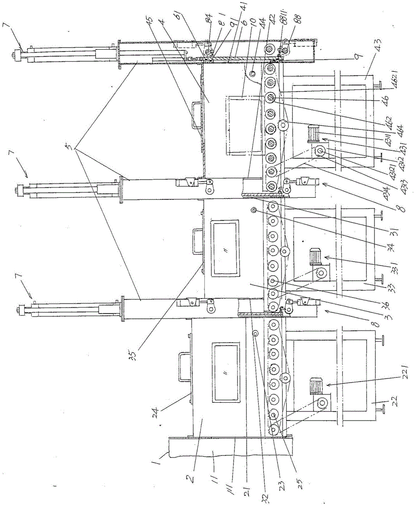
[0023] In the following descriptions, all concepts related to directionality or orientation of up, down, left, right, front and rear are in the form of figure 1 As far as the position and state of the present invention are concerned, it cannot be understood as a special limitation on the technical solution provided by the present invention.

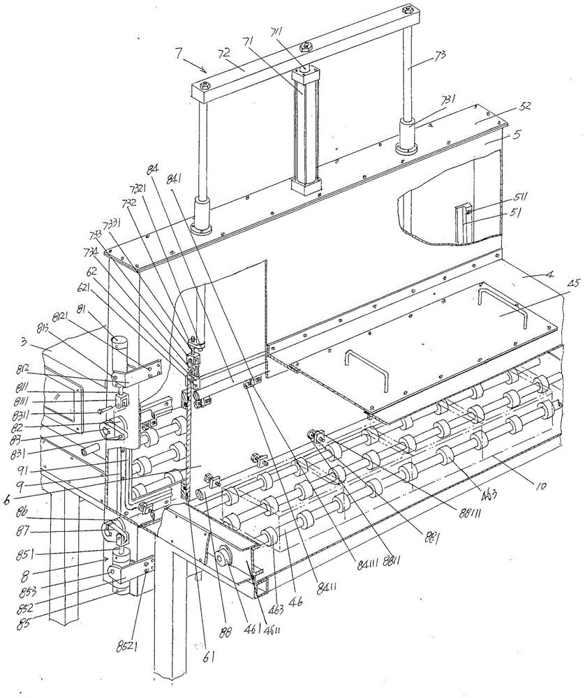
[0024] See figure 1 , showing a furnace body 1, an inlet gas chamber box body 2, a left displacement chamber 3 and a right displacement chamber 4 belonging to the structural system of an elect...


PUM


Abstract

The invention relates to a replacement chamber sealing apparatus for an electronic material firing furnace, and belongs to the technical field of an electronic kiln. The electronic material firing furnace comprises a furnace body, an inlet gas chamber box body, a left replacement chamber and a right replacement chamber; the inlet gas chamber box body is connected with the furnace body and is communicated with a hearth; the left replacement chamber is formed corresponding to a position of a cavity port of the inlet gas chamber box body and is communicated with the inlet gas chamber box body; the right replacement chamber is formed corresponding to a position of a left replacement chamber inlet of the left replacement chamber and is communicated with the left replacement chamber; the replacement chamber sealing apparatus comprises a replacement chamber door box; a replacement chamber lifting mechanism is arranged in the replacement chamber door box; and the replacement chamber sealing apparatus is characterized by further comprising a replacement chamber door external force application mechanism which is arranged at the front side or the rear side of the replacement chamber door box and is matched with one side of a replacement chamber door, which is back to a doorframe sealing ring. The replacement chamber sealing apparatus has a good sealing effect, ensures a vacuumizing effect, saves protection gas filled into the inlet gas chamber box body and the left and right replacement chambers and ensures atmosphere balance, and firing quality of an electronic material is improved.

Description

technical field [0001] The invention belongs to the technical field of electronic kilns, and in particular relates to a sealing device for a replacement chamber of an electronic material firing furnace. Background technique [0002] The aforementioned electronic materials include electronic powders and electronic bodies made of electronic powders, such as colored phosphors, lamp powders, barium titanate, strontium titanate, yttrium trioxide, zirconia, alumina, Bismuth oxide, aluminum zirconate titanate, lithium iron phosphate and ferrite carbon powder, etc.; the electronic body refers to the electronic product blank that is pressed by the electronic powder material and is to be fired in the furnace, typically such as ferrite It is a ferrite blank formed by pressing bulk magnetic powder after adding adhesive. The former (i.e. electronic powder) is usually loaded into a sagger and introduced into an electronic material firing furnace for firing, while the latter is usually st...

Claims


Application Information

Patent Timeline
IPC IPC(8): F27D1/18
CPCF27D1/1866
Inventor 戴青杨国栋
Owner SUZHOU HUIKE EQUIP CO LTD
Learn More