Series feed type waveguide corrective network

A technology of correction network and waveguide, applied in the field of correction network, can solve the problem of weak coupling degree of series-fed correction network, and achieve the effect of good directionality

Active Publication Date: 2016-05-04
CHINA ELECTRONIC TECH GRP CORP NO 38 RES INST
View PDF14 Cites 11 Cited by
  • Summary
  • Abstract
  • Description
  • Claims
  • Application Information

AI Technical Summary

Problems solved by technology

[0007] The technical problem to be solved by the present invention is to provide a high-coupling (about 30dB) series-fed correction network to solve th

Method used


Image

  • Series feed type waveguide corrective network
  • Series feed type waveguide corrective network
  • Series feed type waveguide corrective network

Examples


Embodiment 1

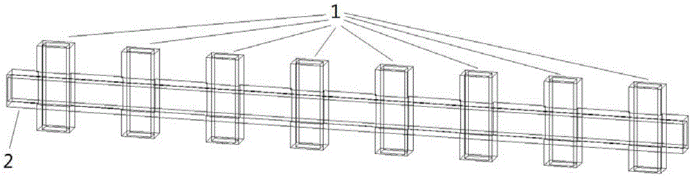
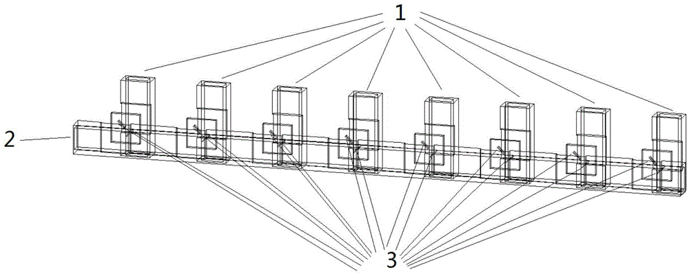
[0028] A basic example is an 8-way correction network. figure 1 It is the appearance rendering, figure 2 is the corresponding layered graph.

[0029] The correction network includes a main waveguide 1, a correction waveguide 2 and a coupling hole 3.

[0030] Such as figure 2 As shown, eight main waveguides 1 are perpendicular to one correction waveguide 2 . The broadsides of the main waveguide 1 and the correction waveguide 2 have 8 overlapping areas, and there are 8 pairs (16) of coupling holes on them.

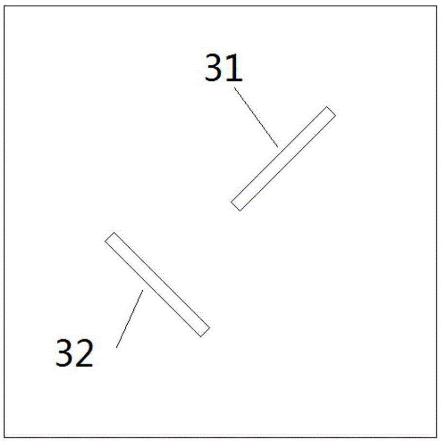
[0031] Such as image 3 As shown, the coupling hole 31 and the coupling hole 32 are on a diagonal of the square overlapping area of ​​the main waveguide and the correction waveguide. The distance between the two centers is 1 / 4 waveguide wavelength. The length is about 1 / 4 waveguide wavelength, and the width is about 1 / 40 waveguide wavelength. The coupling hole 31 is along the diagonal direction; the coupling hole 32 is perpendicular to the diagonal direction.

[00...

Embodiment 2

[0036] Figure 8 The layered diagram of Embodiment 2 is given. The difference from Embodiment 1 is that a ridge waveguide is used.

[0037] The correction network is simulated by HFSS11.0 (a high-frequency structure simulation software developed by Ansoft Company), which is recognized in the industry. The results show that the correction network has a coupling degree of about -28dB within 6% of the bandwidth.


PUM

PropertyMeasurementUnit
Couplingaaaaaaaaaa

Abstract

The invention discloses a series feed type waveguide corrective network. The series feed type waveguide corrective network adopts waveguide type main transmission lines and a coupling transmission line, which have the same type and broadside size, the main transmission lines and the coupling transmission line are vertically crossed and share one public wall, and two coupling holes whose centers are located on a diagonal are arranged in each public wall. Different coupling quantities can be realized through fine tuning of the sizes and the offsets of the coupling holes. In comparison with the prior art, the series feed type waveguide corrective network has the following advantages that the coupling degree is larger (about -30dB or larger), the directionality is good (better than -16dB), and the series feed type waveguide corrective network is used for correcting inconsistency of channels in a phased-array antenna system and is suitable for a phased-array system at high frequency (Q waveband or above) and can be used as a corrective network for a phased-array communication antenna system.

Description

technical field [0001] The invention relates to the technical realization of a correction network, in particular to a series-fed waveguide correction network. Background technique [0002] In a phased array antenna system, the pattern information is the result of combining signals from multiple channels. In order to synthesize an accurate pattern, it is necessary to correct the amplitude and phase characteristics of each channel, that is, to obtain the inherent relative amplitude and phase information of each channel. In operation, the amplitude and phase modulation of each channel needs to subtract the inherent relative amplitude and phase information. [0003] In the correction system, due to the limitation of the dynamic range of the correction receiver, only when the power of the correction signal is within a certain range can the accuracy of phase detection be guaranteed. In the high-frequency (Q-band and above) phased array system, the feeder loss is relatively large...

Claims


Application Information

Patent Timeline
IPC IPC(8): H01Q3/34H01Q21/00
CPCH01Q3/34H01Q21/00
Inventor 高初赖清华彭兰苗菁强云飞
Owner CHINA ELECTRONIC TECH GRP CORP NO 38 RES INST
Why Eureka
Try Eureka