
Built-in pilot operated solenoid valve

A pilot solenoid valve, main valve technology, applied in the direction of lift valve, valve details, safety valve, etc., can solve problems such as inability to meet multiple starts, repeated use, adverse effects of assembly structure, inconvenient assembly testing, etc., to reduce the product. Structural size and weight, reduction of product size and weight, constant flow resistance effect

Active Publication Date: 2016-05-11
XIAN AEROSPACE PROPULSION INST
View PDF7 Cites 14 Cited by
  • Summary
  • Abstract
  • Description
  • Claims
  • Application Information

AI Technical Summary

Problems solved by technology

However, the electric explosion valve is a one-time work product, which cannot meet the requirements of multiple starts and repeated use, and brings a lot of inconvenience to the final assembly test
In addition, the electric explosion valve is driven by gunpowder, which will produce a large impact when it works, which will have an adverse effect on the assembly structure
[0003] There are also systems that try to use solenoid valves instead of electric explosion valves as high-pressure gas circuit switching valves. Due to their small diameter, heavy weight, and high energy consumption, their applications are greatly limited.
Or use a pilot solenoid valve or a self-locking valve, which requires an independent control medium, which makes the system complex, and there are also exhaust holes in the structure, and the impulse generated by the exhaust action will adversely affect the aircraft's operating attitude

Method used


Image

  • Built-in pilot operated solenoid valve
  • Built-in pilot operated solenoid valve
  • Built-in pilot operated solenoid valve

Examples


Embodiment Construction

[0039] The present invention will be further described in detail below in conjunction with the accompanying drawings and embodiments.

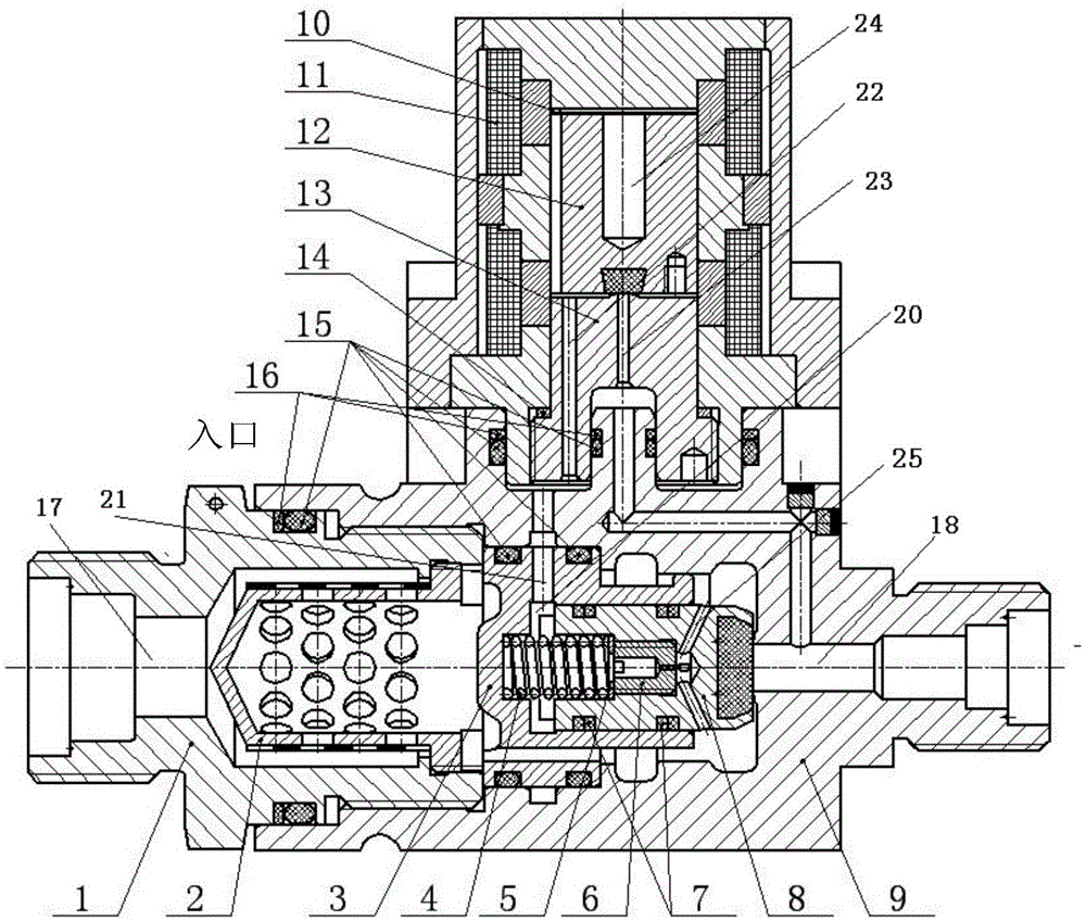
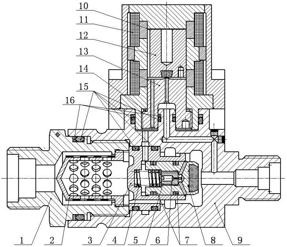
[0040] Such as figure 1 As shown, a built-in pilot solenoid valve with self-locking function, including nozzle 1, filter 2, valve sleeve 3, cylindrical spring 4, spring force adjustment pad 5, current limiting nail 6, baffle ring 7, main valve Core 8, main valve body 9, magnetic isolation pad 10, auxiliary valve coil assembly 11, auxiliary valve core 12, auxiliary valve seat 13, stroke adjustment pad 14, O-shaped rubber sealing ring 15, retaining ring 16, etc.

[0041]Installation relationship: magnetic isolation pad 10, auxiliary valve coil assembly 11, auxiliary valve core 12, auxiliary valve seat 13, stroke adjustment pad 14 are pre-installed as auxiliary valves, and the valve core can be adjusted by selecting magnetic isolation pads and stroke adjustment pads of different thicknesses The size of the initial air gap and working air gap at ...


PUM


Abstract

The invention discloses a built-in pilot operated solenoid valve with a self-locking function. The built-in pilot operated solenoid valve mainly consists of a primary valve body, a filter neck, a filter, a valve bush, a cylindrical spring, a spring force regulating pad, a current-limiting pin, current blocking rings, a primary valve element, a secondary valve coil assembly, a magnetism isolating pad, a secondary valve element and a secondary valve seat, wherein a secondary valve adopts a coil and permanent magnet combined drive source, has a bistable-state passive self-holding function, and power can be provided for state shifting by two coils. By virtue of matching between mounting force of the current-limiting pin and mounting force of the cylindrical spring, reliable action of a primary valve is realized. Under a small-flow working condition, a medium can flow to the downstream through a channel between the current-limiting pin and the secondary valve. A reverse sealing structure made of a metal-hard plastic can give consideration to gastight requirements of high-pressure and low-pressure working conditions. The product can be used gas and liquid-path switch valves with large-flow multi-action needs, and is especially suitable for a high-pressure medium. By virtue of interface adaptive improvement, the built-in pilot operated solenoid valve further can be used as a control valve of an attitude and orbit control liquid rocket engine.

Description

technical field [0001] The invention relates to a pilot solenoid valve, which can be used as an isolation valve of a liquid rocket engine supply system or a high-pressure gas cylinder of a cold air engine system, a switch valve of a pneumatic or hydraulic system pipeline, and can also be used as a position, Orbital control power system liquid rocket motor control valve. Background technique [0002] In the liquid rocket engine supply system or air-conditioning engine system, due to the high inflation pressure of the gas cylinder and high requirements for the sealing performance and working reliability of the gas cylinder isolation valve, the gas cylinder isolation valve usually adopts an electric explosion valve with good sealing performance and reliable operation. valve. However, the electric explosion valve is a one-time work product, which cannot meet the requirements of multiple starts and repeated use, and brings a lot of inconvenience to the final assembly test. In a...

Claims


Application Information

Patent Timeline
Patent Type & Authority Applications(China)
IPC IPC(8): F16K1/00F16K17/30F16K31/08F16K31/36F16K27/02B01D35/04
CPCB01D35/04F16K1/00F16K17/30F16K27/029F16K31/0655F16K31/082F16K31/36
Inventor 张思坤宋会玲罗大亮孙亮袁洪滨曾维亮白少卿
Owner XIAN AEROSPACE PROPULSION INST
Learn More