Itinerant recovery system and method for sensible heat of discharged liquid calcium carbide
A recovery system and heat flow technology, applied in furnaces, waste heat treatment, furnace components, etc., can solve the problems of increasing plant area, poor recovery effect, and low investment, so as to improve production efficiency, shorten cooling time, and eliminate pollution. Effect
- Summary
- Abstract
- Description
- Claims
- Application Information
AI Technical Summary
Problems solved by technology
Method used
Image
Examples
Embodiment 1
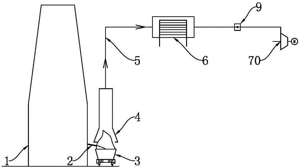
[0031] like figure 1 As shown, in order to solve the problem of calcium carbide sensible heat recovery, the present invention provides a liquid calcium carbide flow recovery system for sensible heat. The system includes a calcium carbide furnace 1, a launder 2 and a calcium carbide pot 3. One end of the launder 2 is connected to the liquid outlet of the calcium carbide furnace 1. , the other end extends to the calcium carbide pot 3; the innovation of the present invention is: the system also includes a wind cover 4, an air duct 5, a heat-using equipment 6 and a recovery induced draft fan 70, and the calcium carbide pot 3 is provided with a wind cover 4, and the wind cover 4 The upper end is connected to the inlet of the air duct 5, and the outlet of the air duct 5 is installed with a recovery induced draft fan 70, and the air duct 5 is connected to the wind cover 4, the heat-using equipment 6, and the recovery induced draft fan 70 in turn; Convective heat exchange and heat tra...
Embodiment 2
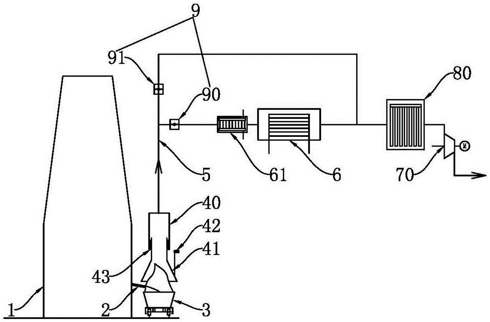
[0035] like figure 2 As shown, the structure of the second embodiment is basically the same as that of the first embodiment. The difference is that in this embodiment, the windshield 4 includes a fixed windshield 40 and a movable windshield 41 arranged up and down, and the upper end of the fixed windshield 40 is connected to the windshield. Pipe 5 inlet, movable wind cover 41 is connected with lifting mechanism 42, and upper end stretches in the fixed wind cover 40, and the sealing between fixed wind cover 40 lower end and movable wind cover 41 upper end, in the present embodiment, lifting mechanism 42 is hoisting machine, A sealing structure 43 is arranged between the fixed wind cover 40 and the movable wind cover 41, and the effect of the sealing is to prevent the outside cold wind from entering and the hot wind from leaking out; 41 and the distance between the calcium carbide pot 3, thereby changing the induced air volume and controlling the induced air temperature to be s...
Embodiment 3
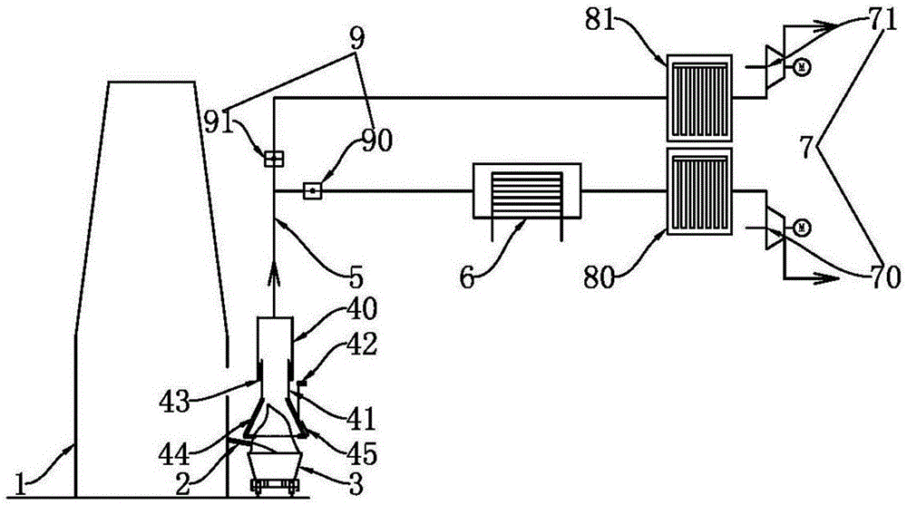
[0042] The structure of the third embodiment is basically the same as that of the second embodiment, the difference is: as figure 1 , 3 As shown, in this embodiment, the air duct 5 connected to the upper end of the fixed wind cover 40 forms a parallel recovery pipeline and a discharge pipeline through a tee, and the recovery pipeline is connected to the recovery valve 90, the heat-using equipment 6, and the recovery dust collector in sequence. 80. Recover the induced draft fan 70, and the discharge pipeline is connected to the discharge valve 91, the discharge dust collector 81, and the discharge induced draft fan 71 in sequence. The recovery induced draft fan 70 and the discharge induced draft fan 71 of this embodiment are two independent systems respectively, the recovery induced draft fan 70 is used for recovering the sensible heat of liquid calcium carbide, and the discharge induced draft fan 71 is used for discharging dust when the furnace opening and the furnace opening ...
PUM
 Abstract
Description
Claims
Application Information
 - R&D
- Intellectual Property
- Life Sciences
- Materials
- Tech Scout
- Unparalleled Data Quality
- Higher Quality Content
- 60% Fewer Hallucinations
Browse by: Latest US Patents, China's latest patents, Technical Efficacy Thesaurus, Application Domain, Technology Topic, Popular Technical Reports.
© 2025 PatSnap. All rights reserved.Legal|Privacy policy|Modern Slavery Act Transparency Statement|Sitemap|About US| Contact US: help@patsnap.com


