
Solar cell module and preparation method thereof

A technology of solar cells and components, applied in the field of solar cells, can solve the problems of easy cracking of cells, non-green materials, and high cost of TPT backplanes, and achieve the effects of ensuring photoelectric conversion efficiency, simple and easy preparation, and high photoelectric conversion efficiency

Active Publication Date: 2016-05-11
BYD CO LTD
View PDF9 Cites 7 Cited by
  • Summary
  • Abstract
  • Description
  • Claims
  • Application Information

AI Technical Summary

Problems solved by technology

[0003] First: The backplane is a polymer backplane material with a certain water vapor transmission rate. Water vapor and corrosive gases in the environment can enter the module through the backplane, corrode the battery sheet and ribbon, and reduce the life of the module; Second: TPT backplanes with better performance cost a lot, and ordinary non-Tedler backplanes are prone to yellowing, cracking, and pulverization after a period of use, which will affect the power and life of the components. The reason also lies in this; thirdly, the wear resistance of polymer materials is low. In the windy and sandy area, the anti-aging layer on the backplane is quickly worn away, causing the PET layer (or copper functional layer) to be exposed to the air. The PET layer is more prone to wear, and the overall wear resistance of the component is low; fourth, the backplane itself is a flexible material, and there is basically no physical protection for the battery on the back, and the battery is easy to crack when it is under pressure or impact; fifth, EVA Although a UV absorber is added in the film, the UV absorber will be gradually consumed under long-term outdoor exposure.
Under the combined action of ultraviolet light and water vapor, EVA will degrade and turn yellow, reduce the power output of the module, and produce small molecules such as acetic acid, which will also corrode the ribbon and the battery, shorten the life of the module and reduce the efficiency
[0004] In addition, battery sheets and ribbons are usually welded with Sn and Pb alloys, but Sn and Pb alloys contain Pb, which pollutes the environment and is not a green material, which is not conducive to popularization and use.

Method used


Image

  • Solar cell module and preparation method thereof
  • Solar cell module and preparation method thereof
  • Solar cell module and preparation method thereof

Examples


preparation example Construction

[0132] During the preparation process of the solar cell module provided by the present application, the conductive wire 32 can be welded to the sub-grid line 312 and the back electrode on the battery sheet first, and then each layer is stacked and laminated.

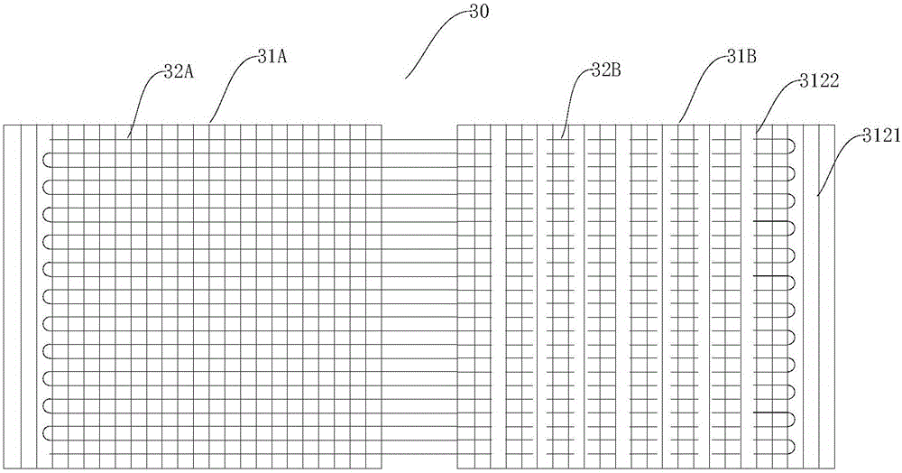
[0133] In a specific embodiment of the present invention, the solar cell module 100 includes an upper cover plate 10 , a front adhesive film layer 20 , a cell array 30 , a back adhesive film layer 40 and a water vapor insulating back sheet 50 . The battery slice array 30 includes a plurality of battery slices 31, and the adjacent battery slices 31 are connected by a plurality of conductive wires 32. The conductive wires 32 are formed by metal wires S extending back and forth between the surfaces of adjacent battery slices. The conductive wires 32 Welding with the auxiliary grid lines, the front adhesive film layer 20 is in direct contact with the conductive lines 32 and fills between adjacent conductive lines 32 .

[013...

example 1

[0174] Example 1 is used to illustrate an example of the solar cell module 100 of the present application and its manufacturing method.

[0175] (1) Preparation of conductive wire

[0176] Attach a layer of 50%Sn-48%Bi-1.5%Ag-0.5%Cu alloy layer (melting point is 160 ℃) on the surface of the copper wire, wherein the cross-sectional area of ​​the copper wire is 0.04mm 2 , the thickness of the alloy layer is 16 microns, thereby making the conductive wire.

[0177] (2) Preparation of solar cell module 100

[0178] Provide a POE film layer with a size of 1630×980×0.5mm (melting temperature is 65°C), and accordingly provide a glass plate with a size of 1633×985×3mm and 60 pieces of polycrystalline silicon cells with a size of 156×156×0.21mm Tablet 31. The battery sheet 31 has 91 auxiliary grid lines (made of silver, with a width of 60 microns and a thickness of 9 microns), each auxiliary grid line basically runs through the battery sheet 31 in the longitudinal direction, and the ...

example 2

[0181] The difference between example 2 and example 1 is:

[0182] Arrange the battery slices 31 in the form of matrix, and between two adjacent battery slices 31, adopt such as Figure 14 In the drawing method shown, 15 parallel metal wires are tensioned through the clip at the end of each metal wire, and the battery sheet is flattened. The tension of the clip is 2N. Each of the 15 parallel metal wires is It is individually welded to the sub-grid on the front of one battery sheet 31 and welded to the back electrode on the back of the other battery sheet, and the distance between adjacent conductive lines that are parallel to each other is 9.9 mm. Thus, a solar cell module was produced.


PUM


Abstract

The invention discloses a solar cell module and a preparation method thereof. The solar cell module comprises an upper glass board, a front adhesive film layer, a solar cell array, a back adhesive film layer and a backboard which are laminated in turn. The backboard is a water vapor insulating backboard. Water vapor transmittance of the water vapor insulating backboard is less than 0.1mg / m<2> / day. The solar cell array includes multiple cells and conductive wires. The adjacent cells are connected via the conductive wires. The front surface of each cell is provided with secondary gate lines. The conductive wires are welded with the secondary gate lines via a welding layer. The welding layer contains alloys which include Sn and Bi. According to the solar cell module, the connecting effect of the conductive wires and the cells can be enhanced so that photoelectric conversion efficiency can be guaranteed. Besides, the welded layer can be effectively sealed on the upper glass board, the front adhesive film layer, the back adhesive film layer and a lower glass or metal board so that the cell array can be effectively protected, attenuation of the solar cell module can be alleviated and the service life can be prolonged.

Description

technical field [0001] The invention relates to the field of solar cells, in particular to a solar cell module and a preparation method thereof. Background technique [0002] Regarding the traditional cell matrix, the current main structure: the silver main grid of the battery is welded to the back of the adjacent battery through the welding strip. The main component of the paste for making the grid line is the expensive precious metal silver. Sn-lead alloy copper strips, common components use EVA as the packaging film, and use polymer materials as the backplane. The following defects have been found in long-term use. [0003] First: The backplane is a polymer backplane material with a certain water vapor transmission rate. Water vapor and corrosive gases in the environment can enter the module through the backplane, corrode the battery sheet and ribbon, and reduce the life of the module; Second: TPT backplanes with better performance cost a lot, and ordinary non-Tedler bac...

Claims


Application Information

Patent Timeline
Patent Type & Authority Applications(China)
IPC IPC(8): H01L31/048H01L31/049H01L31/05H01L31/0224
CPCH01L31/022433H01L31/048H01L31/0512H01L31/042Y02E10/50H01L31/022425H01L31/0488H01L31/0508H01L31/049
Inventor 孙翔王申存薛金鑫姜占锋
Owner BYD CO LTD
Learn More