
Z-axis tool setting gauge

A tool setting instrument and Z-axis technology, applied in the direction of instruments, signal transmission systems, automatic control devices, etc., can solve the problems of reducing the service life of the tool head, high cost, high technical requirements, etc., to avoid interference, avoid serious damage, Solve cumbersome effects

Inactive Publication Date: 2016-05-11
QILU UNIV OF TECH
View PDF6 Cites 6 Cited by
  • Summary
  • Abstract
  • Description
  • Claims
  • Application Information

AI Technical Summary

Problems solved by technology

[0004] In order to make up for the deficiencies in the prior art, the present invention provides a Z-axis tool setting instrument to solve the problem of the high cost and high technical requirements of existing tool setting auxiliary tools, and the relatively low efficiency of tool setting every time. Direct contact with the cutter head, reducing the service life of the cutter head

Method used


Image

  • Z-axis tool setting gauge
  • Z-axis tool setting gauge

Examples


Embodiment Construction

[0027] Accompanying drawing is a kind of specific embodiment of the present invention.

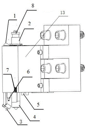
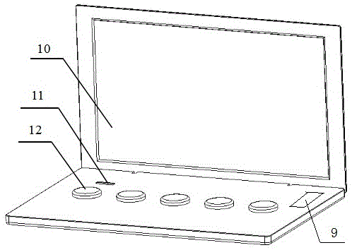
[0028] The Z-axis tool setting instrument of the present invention includes a level 1, a single-chip microcomputer 2, a camera 3, a ball head pressure sensor 4, an ultrasonic ranging sensor 5, an LED light 6, a Z-axis miniature sliding table 7, a transmitting module device 8, and a wireless receiver. A module device 9 , a liquid crystal display 10 , a physical button 11 and a prompt light 12 .

[0029] The Z-axis tool setting instrument of the present invention includes three main functional parts of a monitoring operation part, an acquisition work part and a data transmission part connected to each other, and the monitoring operation part includes a liquid crystal display screen 10 connected to each other, a physical control button 11 and a wireless receiving module Device 9; the acquisition part includes a level 1 installed on the bracket 13, a ball pressure sensor 4, an ultrasonic dista...


PUM


Abstract

The invention discloses a Z-axis tool setting gauge, belonging to the factory equipment technical filed, and comprises a monitoring operation portion, a collection work portion, and a data transmission portion. A main body portion is fixed directly above a cutter through holt hoop iron; other components are hidden in a housing through a small sliding table. The monitoring operation portion comprises a liquid crystal display screen and a physical control button. The collection work portion comprises a level, a bulb pressure transducer, an ultrasonic ranging inductor, an LED lamp, and a camera. The data transmission portion comprises a 51 single-chip microcomputer, a wireless receiver, and an emission module apparatus. By utilizing a shade and shadow coincidence principle, an auxiliary tool setting mode is innovated based on a control system theory, and only one-step installation is required, thereby solving the problems of repeated tool setting operation and serious damage to a cutter bit. The Z-axis tool setting gauge can be applied to a series of factory devices requiring Z-axis tool setting.

Description

technical field [0001] The invention relates to components of engraving machines and numerically controlled machine tools, in particular to a Z-axis tool setting instrument. Background technique [0002] With the rapid development of modern society, CNC machining technology is playing an increasingly important role in industrial production. However, tool setting is often involved in NC machining, and the quality of its handling directly affects the precision of parts processing, and also affects the safe operation of machine tools (such as tool collision). At present, the conventional manual trial cutting and knife setting method has low efficiency, low precision, waste of materials, and requires certain work experience. The existing auxiliary tools for tool setting not only have high cost and high technical requirements, but also need to set the tool again every time they are used, so the efficiency is relatively low. And when setting the knife, the direct contact between...

Claims


Application Information

Patent Timeline
IPC IPC(8): H04N7/18G08C17/02B23Q17/22B23Q15/22
CPCB23Q15/22B23Q17/2266G08C17/02H04N7/18
Inventor 宋雪丽卢世斌范林强李宸唐晓腾衣品侨
Owner QILU UNIV OF TECH
Learn More