Gradient utilization system by medium/low-temperature geothermal energy assisted carbon dioxide capture

A technology of carbon dioxide and geothermal energy, applied in the direction of direct carbon dioxide emission reduction, inorganic chemistry, energy input, etc., can solve the problems of power plant power generation efficiency decline, large heat energy consumption, etc., and achieve the effect of avoiding waste, realizing stable operation, and eliminating adverse effects

Inactive Publication Date: 2016-05-18
TIANJIN UNIV
View PDF3 Cites 4 Cited by
  • Summary
  • Abstract
  • Description
  • Claims
  • Application Information

AI Technical Summary

Problems solved by technology

However, CO 2 The capture process needs to consume a lot of heat energy. For the MEA method, the energy consumption of the reboiler reaches 3-4GJ / ton CO 2 , its heat demand usually comes from the extraction steam in the low-pressure cylinder of the steam turbine in the power plant, which causes the power generation efficiency of the power plant to drop by 15-30%

Method used


Image

  • Gradient utilization system by medium/low-temperature geothermal energy assisted carbon dioxide capture
  • Gradient utilization system by medium/low-temperature geothermal energy assisted carbon dioxide capture

Examples


Embodiment 1

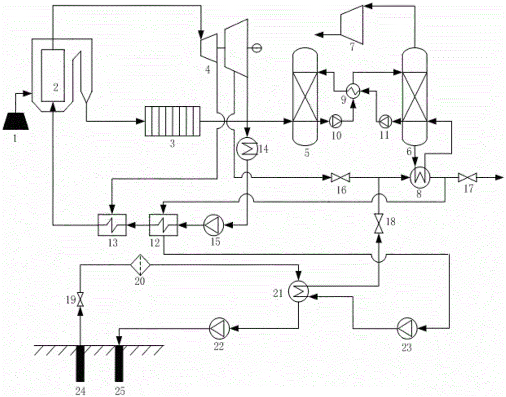
[0022] When the medium and low temperature geothermal energy is used in stages, the connection relationship between the medium and low temperature geothermal energy subsystem, the power generation subsystem and the carbon dioxide capture subsystem is as follows: figure 1 As shown, after the production well 24 in the medium and low temperature geothermal energy subsystem is sequentially connected in series through the first control valve 19, the filter 20, the geothermal heat exchanger 21 and the third pump 22, the geothermal water after heat exchange is regenerated Backfilling into the injection well 25, to keep the balance of geothermal water. The working fluid at the outlet of the heat source end of the reboiler 8 is connected to the inlet of the heat source end of the low-pressure feed water heat exchanger 12, and the outlet of the heat source end of the low-pressure feed water heat exchanger 12 is connected to the inlet of the second pump 23, thereby realizing medium and lo...

Embodiment 2

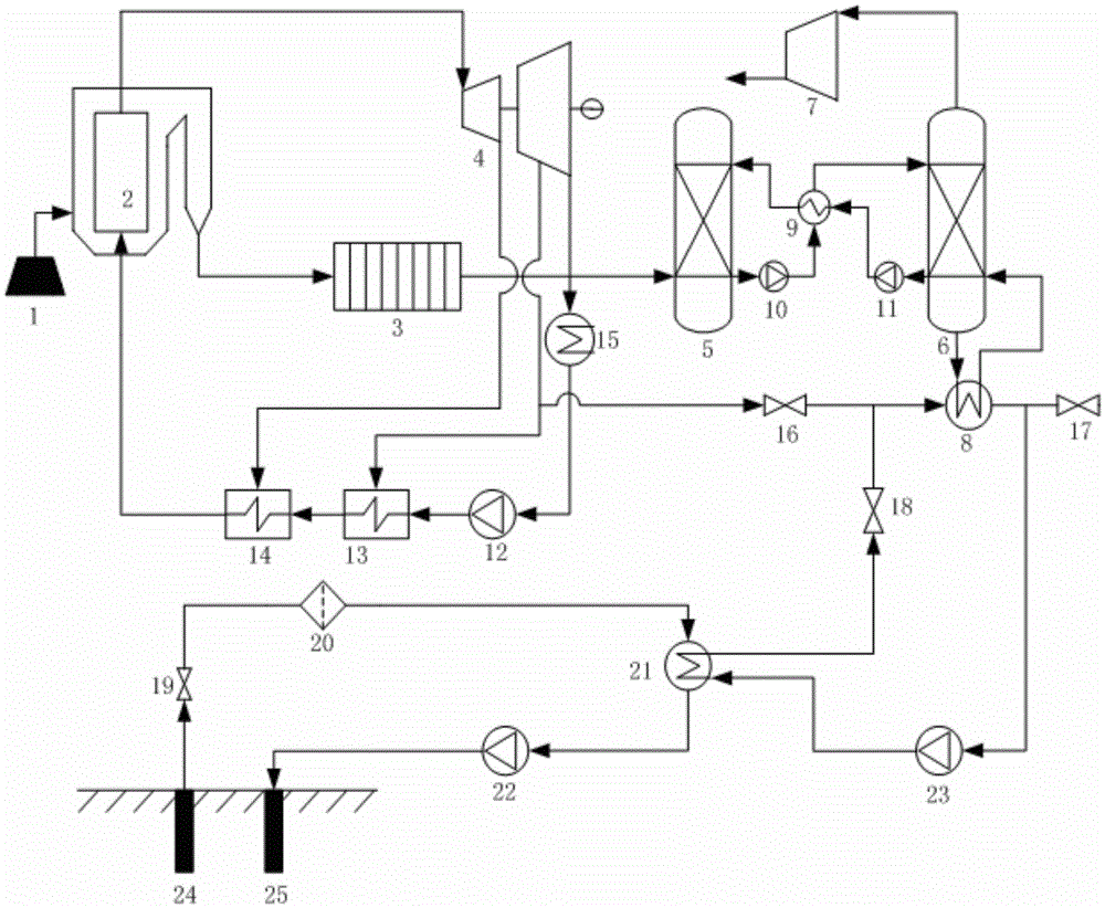
[0024] When the medium and low temperature geothermal energy can only realize the energy supply and utilization of the reboiler 8, the connection relationship between the medium and low temperature geothermal energy subsystem, the power generation subsystem and the carbon dioxide capture subsystem is as follows: figure 2 As shown, the outlet of the heat source end of the reboiler 8 is directly connected to the second pump 23, the outlet of the second pump 23 is connected to the inlet of the low-temperature end of the geothermal heat exchanger 21, and the outlet of the low-temperature end of the geothermal heat exchanger 21 is connected to the into the steam extraction pipeline and connected to the heat source end of the reboiler 8 to provide the required thermal energy for the reboiler 8. The connection method of embodiment 2 only uses geothermal energy to provide the heat required by the reboiler 8, which has the advantage of simplifying the system structure and reducing the ...


PUM


Abstract

The invention discloses a gradient utilization system by medium / low-temperature geothermal energy assisted carbon dioxide capture. The system is mainly composed of a power plant power generation subsystem, a carbon dioxide capture subsystem, a medium / low-temperature geothermal energy subsystem and related control components. All the parts are mainly connected by a fume cleaning device, a reboiler and a geothermal heat exchanger, thereby forming an overall system. The operating fluid subjected to heat exchange with the geothermal fluid sequentially passes through the reboiler and the power plant low-pressure water supply heat exchanger, thereby providing heat for the reboiler in the carbon dioxide capture process, providing heat requirements for the power plant low-pressure water supply heat exchanger, and lowering the extraction steam of power plant low-pressure water supply heating. The system sufficiently implements the gradient utilization of geothermal energy, can greatly lower the energy consumption by extracting steam from the power plant steam turbine, implements the double effects of renewable energy source utilization and power plant carbon dioxide emission reduction on the premise of maintaining the stability of the power plant, and vigorously promotes the large-scale application of the national geothermal energy and flue gas capture integration technology.

Description

technical field [0001] The invention relates to a medium and low temperature geothermal energy assisted carbon dioxide capture integration technology, in particular to the integration of medium and low temperature geothermal energy with the carbon dioxide capture subsystem in the flue gas of a power plant and the power plant feed water heating system, using geothermal energy to provide the carbon dioxide capture subsystem Energy compensation, while providing low-temperature heat to the water heating system, while realizing cascaded utilization of geothermal energy, effectively reduces the efficiency drop caused by steam extraction in the power plant. Background technique [0002] CO 2 The capture, utilization and storage of 2 It is a strategic technology and an important way to achieve large-scale CO at this stage 2 It is the most direct technology for emission reduction and also the carbon capture technology with the greatest emission reduction potential in the future. A...

Claims


Application Information

Patent Timeline
Patent Type & Authority Applications(China)
IPC IPC(8): C01B31/20B01D53/78B01D53/62F23J15/02C01B32/50
CPCB01D53/62B01D2251/60B01D2251/80B01D2257/504B01D2258/0283B01D2259/124F23J15/02F23J2215/50Y02A50/20Y02C20/40Y02E20/32Y02P20/133Y02P20/151
Inventor 王甫赵军严晋跃邓帅孙太尉
Owner TIANJIN UNIV
Why Eureka
Try Eureka