Ultralow-temperature auto-cascade type refrigerating device and refrigerating method
A refrigeration device and a self-cascading technology, which is applied in the field of ultra-low temperature self-cascading refrigeration devices, can solve the problems of difficulty in quickly balancing refrigerant gas, delaying the time of target temperature, affecting the refrigeration effect of the system, etc., and achieves good energy-saving effect, The effect of small mutual influence and shortened start-up time
- Summary
- Abstract
- Description
- Claims
- Application Information
AI Technical Summary
Problems solved by technology
Method used
Image

Examples
Embodiment 1
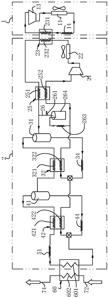
[0077] refer to figure 1 , an ultra-low temperature self-cascading refrigeration device, comprising a pre-cooling unit 1 and a multi-element refrigerant circulation unit 2.
[0078] The pre-cooling unit 1 comprises a pre-cooling compressor 13, a pre-cooling condenser 11, a pre-cooling throttling element 14 and a pre-cooling heat exchanger 23 connected sequentially by pipelines to form a circulation system; in the present embodiment, the pre-cooling condenser 11 It is an air-cooled condenser, and the pre-cooling throttling element 14 adopts a capillary throttling valve.
[0079] The multi-component refrigerant cycle unit 2 includes a main compressor 21, a main condenser 22, a precooling heat exchanger 23, a heat regenerator 25, a first gas-liquid separator 31, a first sub-heat exchanger 32, a second gas-liquid separator 41 and the second sub-heat exchanger 42, the main throttling element 51 and the main evaporator 60.
[0080] The pre-cooling heat exchanger 23 in the pre-cool...
Embodiment 2
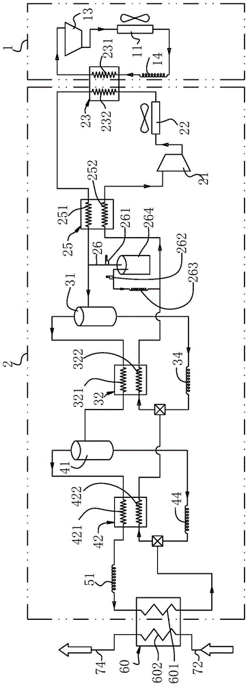
[0089] refer to figure 2 , this embodiment is an improvement on the basis of Embodiment 1, and an on-off valve 262 is also provided between the liquid storage tank 264 and the second throttling element 263 . The switch valve 262 adopts a solenoid valve to facilitate automatic control and remote operation of the device.
Embodiment 3
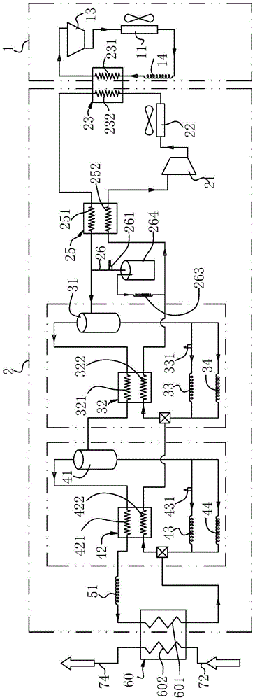
[0091] refer to image 3 , this embodiment is an improvement on the basis of Embodiment 1. In this embodiment, there are two first sub-throttle elements, and on the basis of the first sub-throttle element B34, an additional The element B34 is connected in parallel with the first sub-throttle element A33, and a first cut-off valve 331 is provided at the inlet end of the first sub-throttle element A33. Of course, three or more first sub-throttling elements can also be provided, and a first disconnect valve can also be arranged at the inlet ends of more first sub-throttle elements.
[0092] There are two second sub-throttle elements, on the basis of the second sub-throttle element B44, add a second sub-throttle element A43 in parallel with the second sub-throttle element B44, and in the second sub-throttle element The inlet end of A43 is provided with a second cut-off valve 431 . Of course, three or more second sub-throttling elements can also be provided, and second disconnect...
PUM
 Abstract
Description
Claims
Application Information
 - R&D
- Intellectual Property
- Life Sciences
- Materials
- Tech Scout
- Unparalleled Data Quality
- Higher Quality Content
- 60% Fewer Hallucinations
Browse by: Latest US Patents, China's latest patents, Technical Efficacy Thesaurus, Application Domain, Technology Topic, Popular Technical Reports.
© 2025 PatSnap. All rights reserved.Legal|Privacy policy|Modern Slavery Act Transparency Statement|Sitemap|About US| Contact US: help@patsnap.com