Annular movable tile kiln flue gas dedusting and desulfurizing apparatuses and methods thereof
A desulfurization device and mobile technology, applied in the field of ring-type mobile brick kiln flue gas dust removal and desulfurization device, can solve the problems of high efficiency, difficult maintenance, consumption of large manpower and material resources, etc.
- Summary
- Abstract
- Description
- Claims
- Application Information
AI Technical Summary
Problems solved by technology
Method used
Image
Examples
Embodiment 1
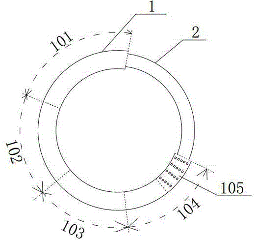
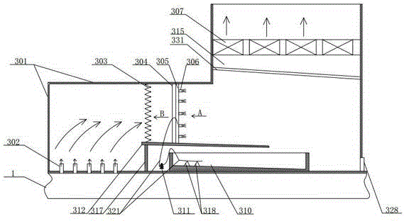
[0068] Embodiment one, see figure 1 , figure 2 , Figure 21 , Figure 22 , the movable kiln body 1 is divided into the kiln body section 104 in the drying area, the kiln body section 103 in the preheating area, the kiln body section 102 in the roasting area, and the kiln body section 101 in the cooling area. The chimney discharge area 105 is set in the kiln body in the drying area end of segment 104, figure 2 Shown is a schematic diagram of the structure of the dust removal and desulfurization device inside the kiln body. The dust removal and desulfurization device is installed in the kiln body section 104 of the drying area, and the closed drainage hood 301 is fixedly installed on the top of the kiln body at the smoke discharge area 105. The top of the kiln body at the discharge area 105 is covered therein and extends for a certain distance along the direction of the kiln body section 103 in the preheating area. The top of the end of the closed drainage hood 301 is provi...
Embodiment 2
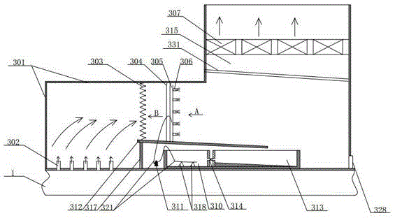
[0069] Embodiment two, see image 3 The difference between the present embodiment and the first embodiment is that: in the present embodiment, a sedimentation tank 313 is provided next to the reaction raw material pool 310, and an overflow communication pipeline 314 communicating with the reaction raw material pool is provided in the sedimentation tank 313, and the overflow communication pipeline 314 There is a one-way valve that flows from the sedimentation tank 313 to the reaction raw material pool 313. The downward inclined end of the step support platform 312 is located above the sedimentation tank 313. The reaction raw material pool is provided with NaOH solution, and the sedimentation tank is provided with Ca(OH) 2 Solution, other specific implementation methods are the same as in Example 1, and will not be repeated.
[0070] The specific working process of the sulfur removal device in this embodiment is as follows: the flue gas at the flue gas discharge area passes thro...
Embodiment 3
[0073] Embodiment three, see Figure 4 , Figure 23 , the difference between this embodiment and Embodiment 1 is: in this implementation, a certain number of front and rear rows of longitudinal beams with equivalent beam spacing are arranged between the step support platform 312 and the closed drainage cover 301, and one end of the front and rear rows of longitudinal beams It is fixed on the top of the kiln body, one end is connected to the closed drainage cover 301, and the front and rear rows of longitudinal beams are arranged in a staggered manner, and the filter screen is arranged between the adjacent front row of longitudinal beams 303-3 and the rear row of longitudinal beams 303-4 In between, a folded filter net is formed, and the mesh number of the folded filter net 303 is between 20-100, wherein there is only one row of vertical beams between the step support platform and the closed drainage hood, and the filter net 303 is fixed on the vertical beams to form Flat filt...
PUM
 Abstract
Description
Claims
Application Information
 - R&D
- Intellectual Property
- Life Sciences
- Materials
- Tech Scout
- Unparalleled Data Quality
- Higher Quality Content
- 60% Fewer Hallucinations
Browse by: Latest US Patents, China's latest patents, Technical Efficacy Thesaurus, Application Domain, Technology Topic, Popular Technical Reports.
© 2025 PatSnap. All rights reserved.Legal|Privacy policy|Modern Slavery Act Transparency Statement|Sitemap|About US| Contact US: help@patsnap.com


