
A processing method and apparatus of coal-firing gas

A coal-fired flue gas and treatment method technology, which is applied in the direction of combined devices, separation methods, chemical instruments and methods, etc., can solve problems such as the inability to achieve CO2 removal, achieve significant desulfurization effects, improve heat exchange efficiency, and high added value Effect

Inactive Publication Date: 2008-04-09
ZHENGZHOU UNIV
View PDF0 Cites 23 Cited by
  • Summary
  • Abstract
  • Description
  • Claims
  • Application Information

AI Technical Summary

Problems solved by technology

However, so far, no research or production unit in the world has designed and produced a decarbonization device, and the existing desulfurization device cannot achieve CO 2 removal of

Method used


Image

  • A processing method and apparatus of coal-firing gas
  • A processing method and apparatus of coal-firing gas

Examples


Embodiment 1

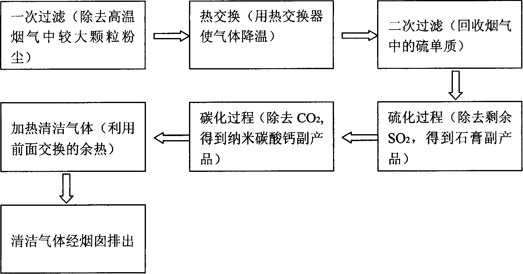
[0051] Coal-fired flue gas from thermal power plants, in which the contents of soot particles, sulfur vapor, sulfur dioxide, and carbon dioxide are 2123mg / m 3 、1859mg / m 3 , 8000mg / m 3 , 700mg / m 3 , first pass the coal-fired flue gas into the primary filter equipment. The filter element is a SiC porous ceramic filter with pores distributed in a three-dimensional network, with a pore size of 100 microns; the SiC porous ceramic filter is supported by a carrier, sealed with a graphite gasket, and connected by a flange. . The solid particles intercepted by filtration fall into the temporary ash bin; the porous ceramic filter is backflushed by pulse backflushing. The dust content of the flue gas from the primary filter device is reduced to 1%, and it enters the heat exchanger. Part of the recovered sensible heat enters the boiler steam circulation system, and part of it heats the gas after wet desulfurization; the outlet temperature of the heat exchanger is controlled at 150°C; ...

Embodiment 2

[0055] Coal-fired flue gas from thermal power plants, in which the contents of soot particles, sulfur vapor, sulfur dioxide, and carbon dioxide are 2123mg / m 3 、1859mg / m 3 、5000mg / m 3 、685mg / m 3 , The coal-fired flue gas is passed into the filter equipment. The filter element is a SiC porous ceramic filter with pores distributed in a three-dimensional network, with a pore size of 100 μm; the SiC porous ceramic filter is supported by a carrier, sealed with a graphite gasket, and connected by a flange. The solid particles intercepted by filtration fall into the temporary ash bin; the porous ceramic filter is backflushed by pulse backflushing. After filtration, the filtration efficiency of soot particles in the flue gas is as high as 90%; 60% recovery of steam sulfur element is achieved, SO 2 30% were adsorbed. The flue gas from the dry filtration device directly enters the heat exchanger, part of the recovered sensible heat enters the boiler steam circulation system, and part...


PUM

PropertyMeasurementUnit
Apertureaaaaaaaaaa
Apertureaaaaaaaaaa

Abstract

The invention relates to a processing method for coal flue gas. Smoke dust particles and sulfur are removed from the coal flue gas through dry filtration, and sulfur dioxide is removed through a wet process, wherein, the dry filtration process comprises the steps that the coal flue gas passes through ceramic filtering materials; the process for removing the sulfur dioxide with a wet method has the steps that the sulfur dioxide is removed through the reaction of the coal flue gas after being processed with a dry method and calcium carbonate serosity. The invention has evident desulfation effect, and a formed accessory substance has very high added value; the invention can rationally use the residual heat of the high temperature coal flue gas; the invention realizes the removing of an element S and the recovery of the high purity, simultaneously performs the decarbonization process, and avoids the environmental pollution; the equipment adopted by the invention is easy to be assembled and disassembled, cleaned, and maintained; the invention resolves the contradiction between the operating costs and the operating effects of the desulfation and the decarbonization, and has huge economic interest and huge application foreground.

Description

(1) Technical field [0001] The invention relates to a treatment method and device for coal-burning flue gas, in particular to the treatment of coal-burning flue gas whose main components are smoke particles, sulfur vapor, sulfur dioxide and carbon dioxide. (2) Background technology [0002] According to the national environmental quality inspection status announced by the State Environmental Protection Administration, the national acid rain (pH value less than or equal to 5.6) pollution is on the rise. Sulfur dioxide emitted as an overhead source from coal-fired power plants is a major cause of acid rain. Controlling air pollutant emissions from coal-fired power plants has become the key to improving China's air quality and controlling acid rain pollution. [0003] At home and abroad, water washing is usually used for desulfurization, that is, the high-temperature flue dust containing sulfur is passed into water, so that the SO contained 2 Dissolve in water. This method n...

Claims


Application Information

Patent Timeline
IPC IPC(8): B01D53/50B01D50/00B01D53/78F23J15/00
CPCY02E20/32
Inventor 张锐王海龙薛红星潘震王立军卢红霞许红亮陈德良关绍康
Owner ZHENGZHOU UNIV
Learn More