Composite foundation and construction method thereof

A construction method and technology of composite foundation, which are applied in the directions of foundation structure engineering, soil protection, sheet pile wall, etc. Density, avoid uneven settlement, reduce the effect of settlement value deviation

Inactive Publication Date: 2016-06-01
王继忠
View PDF5 Cites 5 Cited by
  • Summary
  • Abstract
  • Description
  • Claims
  • Application Information

AI Technical Summary

Problems solved by technology

[0002] At present, composite foundations are widely used in foundation treatment engineering in the field of construction engineering. Among the commonly used composite foundation treatment methods, deep-layer mixing piles and high-pressure rotary grouting piles are traditional treatment methods. The advantages of these two methods are that they are not excavated and can be used Original soil, but it also has its limitations. For example, deep mixing piles have high requirements on soil quality and organic matter content. High, so the overall bearing capacity of its composite foundation is limited
In the high-strength composite foundation, due to the difficulty of passing through the soil layer and sometimes reaching the design depth during the construction of the prefabricated pile body, cast-in-situ concrete piles are often used as the reinforcement of the composite foundation. Concrete pouring technology is used for construction, such as CFG piles, but this kind of construction method uses the soil discharge method when forming holes, which requires on-site soil removal and is likely to cause problems such as empty soil at the bottom of the hole and environmental pollution.
Moreover, most of the bearing capacity of the above three methods comes from the side resistance of the pile, so in order to increase the bearing capacity, the length of the pile body has to be increased, resulting in increased construction costs

Method used


Image

  • Composite foundation and construction method thereof
  • Composite foundation and construction method thereof

Examples


Embodiment Construction

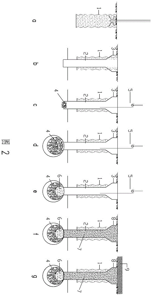
[0020] The present invention will be further described below by specific examples.

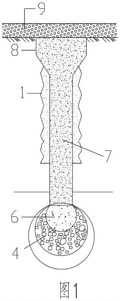
[0021] figure 1 It is a schematic composition diagram of an embodiment of the composite foundation of the present invention, such as figure 1 As shown, the composite foundation includes a pile foundation and its upper cushion layer 8, and the pile foundation is composed of a cement-soil pile body 1 on the periphery, a concrete pile body 7 inside the cement-soil pile body 1, and a pile top diameter expansion part on the top of the concrete pile body 7. 8, and the lower end of the concrete pile body 6 is composed of four parts: the pile end carrier part composed of the tamped reinforcing material 4 and dry hard concrete 5; wherein the diameter of the cement soil pile body 1 on the periphery is 600mm, the length is 6000m, and the concrete pile body 7 The diameter is 400mm, the length is 8000mm, and the volume of the tamped reinforcing material 4 is 0.8m 3 , the volume of tamped dry hard concret...


PUM


Abstract

The invention aims to provide a composite foundation which is high in pile strength, is large in stress area, is capable of improving a pile-soil replacing ratio and sufficiently transferring a pile-end soil body to participate in stress, and a construction method thereof. The composite foundation comprises a pile foundation and an upper cushion layer of the pile foundation, wherein the pile foundation consists of a peripheral cemented soil pile body, an inner concrete pile body, a pile top expanding part and a pile end carrier part; and the diameter of the pile top expanding part is greater than or equal to that of the cemented soil pile body. The invention further discloses a construction method for the composite foundation, wherein the construction method comprises the following steps: (1) stirring a soil body at pile location by adopting a mode of not excavating soil, and spraying cement paste into the soil body to form a cemented soil pile body; (2) before strength of the cemented soil pile body reaches initial setting strength, forming holes in the middle part of the cemented soil pile body by adopting a mode of extruding soil, wherein the hole-forming depth is greater than or equal to depth of the cemented soil pile body; (3) carrying out pile end carrier part construction; (4) carrying out concrete pile body and pile top expanding part construction; and (5) laying the cushion layer on the pile top.

Description

technical field [0001] The application relates to the field of civil engineering, in particular to a composite foundation form and a construction method thereof. Background technique [0002] At present, composite foundations are widely used in foundation treatment engineering in the field of construction engineering. Among the commonly used composite foundation treatment methods, deep-layer mixing piles and high-pressure rotary grouting piles are traditional treatment methods. The advantages of these two methods are that they are not excavated and can be used Original soil, but it also has its limitations, such as deep mixing piles have high requirements on soil quality and organic matter content, high-pressure rotary grouting piles are strictly controlled, and it is easy to cause slurry waste and environmental pollution, and the strength of the piles constructed by these two methods is not high. High, so the overall bearing capacity of its composite foundation is limited. ...

Claims


Application Information

Patent Timeline
Patent Type & Authority Applications(China)
IPC IPC(8): E02D3/08E02D5/50E02D5/62
CPCE02D3/08E02D5/50E02D5/62
Inventor 王继忠
Owner 王继忠
Why Eureka
Try Eureka